background image

13

!

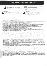
Failure to observe instructions marked in this way 

can cause equipment damage!

WARNING: Failure to observe instructions 

marked in this way will most probably cause 

bodily injury!


Precautions


on


use


of


MAGI


2


series


pumps

1.

Before


installation,


read


the


following


manual


carefully

2.

Failure


to


observe


the


fragments


marked


with


warning


signs


may


cause


bodily


injury,


pump


damage


and


other


property


losses,

for


which


the


producer


takes


no


lability,


including


but


not


limited


to


liability


for


damages.

3.

The


fitter,


maintenance


technician


and


user


have


to


observe


the


local


safety


regulations.

4.

The


user


must


confirm


that


the


installation


and


maintenance


of


the


product


are


performed


by


personnel


having


adequate

knowledge


and


professional


experience


connected


with


the


structure


and


operation


of


heating


systems.

5.

Pumps


cannot


be


installed


in


moist


environment


or


in


places


which


can


be


exposed


to


flooding


with


splattering


water.

6.

To


make


maintenance


easier,


place


a


ball


valve


on


both


sides


of


the


pump.

7.

During


installation


and


maintenance,


cut


off


the


electric


power


supply


from


the


pump.

8.

The


central


heating


circuit


cannot


be


frequently


refilled


with


non-softened


water


to


avoid


accumulation


of


scale


in


the

pipeline.


High


accumulation


of


scale


can


block


the


rotor


of


the


device.

9.

The


pump


cannot


be


run


without


a


heating


medium.

10.

If


the


pump


is


dismounted


from


the


pipeline,


either


discharge


the


heating


medium


from


the


system


or


close


the


ball


valves

cutting


the


pump


off


before


dismounting


to


avoid


possible


burning


with


the


heating


medium.


Please


remember


that


the


heating


medium


can


have


high


temperature


and


pressure.

11.

In


dismounting


the


pump


from


the


pipeline,


the


heating


medium,


which


can


have


high


temperature


and


high


pressure,


will

flow


outside.


Please


be


careful


not


to


cause


bodily


injury


due


to


burning


and


not


to


flood


other


devices.

12.

In


summer


or


when


the


ambient


temperature


is


high,


pay


attention


to


proper


ventilation


in


the


room


where


the


pump


has

been


installed.


It


will


help


prevent


condensation


of


humidity,


which


can


cause


an


electric


failure.

13.

In


winter,


if


the


central


heating


system


where


the


pump


has


been


installed


does


not


work


and


the


ambient


temperature


is

below


0


°


C,


discharge


water


from


the


heating


system.


Please


bear


in


mind


that


freezing


water


can


burst


the


pump


body.

14.

If


the


pump


does


not


operate


for


a


long


time,


close


the


ball


valves


cutting


off


the


pump


and


cut


off


electric


power


supply.

15.

If


the


electric


wire


powering


the


pump


is


damaged,


refer


to


an


authorised


servicing


team


to


replace


it


along


with


its


switch.

16.

If


the


pump


motor


heats


up


excessively


(more


than


usually),


immediately


disconnect


the


pump


from


its


power


source,


close

the


cut


off


valves


and


contact


a


servicing


team.

17.

If


a


pump


failure


cannot


be


removed


according


to


the


manual,


immediately


disconnect


the


pump


from


its


power


supply,


close

the


cut


off


valves


and


immediately


contact


the


local


manufacturer


or


the


servicing


centre.

18.

The


product


must


be


placed


in


a


place


far


away


from


children


and


measures


to


isolate


the


product


must


be


taken


to


avoid

children


touching


it.

19.

The


product


must


be


connected


to


the


electric


mains


equipped


with


efficient


electric


earthing.


The


yellow-green


core


of


the

connection


cable


is


earthing.

20.

The


product


must


be


connected


to


mains


equipped


with


a


residual


current


circuit


breaker


with


tripping


current


In


not

exceeding


30


mA.

21.

The


product


must


be


placed


in


a


dry,


well-ventilated


and


cool


place


and


stored


at


room


temperature.

22.

This


equipment


is


not


intended


for


use


by


persons


(including


children)


with


reduced


motor,


sensory


or


mental


capacities,


or

persons


without


experience


or


not


familiarised


with


the


equipment,


unless


it


is


performed


under


supervision


or


according


to


the


instruction


regarding


operation


provided


by


persons


responsible


for


their


safety.


Attention


should


be


paid


so


that


children


do


not


play


with


the


equipment.

Failure to observe instructions marked in this way 

can cause equipment damage!

!

WARNING!!!

Before proceeding to install the device, carefully read 

the instructions for installation and operation of the 

device. The installation and use of the device must 

conform to the local regulations and this manual.

!

WARNING!!!

People (including children) with limited physical, sensory 

or mental capacity or people without experience or 

knowledge in equipment must use the pump under 

supervision and guidance of the people who can take 

responsibility for their safety.

USE AND CARE GUIDE MAGI 2

Summary of Contents for MAGI 2 25-40/180

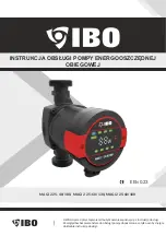
Page 1: ...naj się z instrukcją obsługi Ze względów bezpieczeństwa do obsługi pompy dopuszczone są tylko osoby znające dokładnie instrukcję obsługi INSTRUKCJA OBSŁUGI POMPY ENERGOOSZCZĘDNEJ OBIEGOWEJ MAGI 2 25 40 180 MAGI 2 25 60 130 MAGI 2 25 60 180 EEI 0 23 ...

Page 2: ...aściwą wentylację w pomieszczeniu gdzie jest zainstalowanapompa Pomożetozapobieckondensacjiwilgoci któramożespowodowaćusterkęelektryczną 13 Zimą jeśli system CO gdzie zainstalowano pompę nie pracuje i temperatura otoczenia jest niższa niż 0 C należy opróżnić układgrzewczyzwody Należypamiętać żezamarzającawodamożerozsadzićkorpuspompy 14 Jeśli pompa nie będzie pracować przez długi czas zamknij zawor...

Page 3: ...ysłowego System domowego CO Zaletyinstalacjipomp MAGI 2 Łatwa instalacja i uruchomienie Pompa cyrkulacyjna serii MAGI 2 posiada tryb autoadaptacyjny AUTO ECO ustawienia fabryczne W większości przypadków można uruchomić pompę bez konieczności wprowadzania jakichkolwiek regulacji i automatycznie dostosowaćjądoaktualnychpotrzebsystemu Wysokikomfortużytkowania Niskipoziomhałasupompyicałegosystemu Nisk...

Page 4: ...łączowej wykonaj następujące czynności 1 Odłącz pompę od zasilania elektrycznego 2 Zamknij zawory kulowe odcinające na wlocie i wylocie pompy oraz przeprowadzić dekompresję 3 Poluzuj i usuń cztery śruby mocujące głowicę w korpusie pompy 4 Obróć silnik w żądane położenie i dopasuj cztery otwory na śruby 5 Włożyć cztery śruby z łbem ampulowym do odpowiednich gniazd i dokręcić je OSTRZEŻENIE Czynnik ...

Page 5: ...nymi przepisami Pompa elektryczna musi być podłączona do przewodu uziemiającego Pompa musi być podłączona do zewnętrznego wyłącznika zasilania Minimalna szczelina między stykami wyłącznika powinna wynosić 3 mm Pompa cyrkulacyjna serii MAGI 2 nie wymaga zewnętrznej ochrony silnika Proszę sprawdzić czy napięcie zasilania i częstotliwości odpowiadają parametrom oznaczonym na tabliczce znamionowej pom...

Page 6: ...u pracy Po uruchomieniu przez chwilę zaświecą się wszystkie wskaźniki trybów pracy po czym pompa wejdzie w ostatni uruchomiony przed wyłączeniem tryb pracy Jednokrotne przyciśnięcie przycisku głównego przełącznika zmiany trybu pracy powoduje zmianę trybu wg poniższej kolejności AUTO LPP HPP LCP HCP 1 2 3 Jednokrotne naciśnięcie przycisku spowoduje przejście w kolejny na liście tryb Wejście w dany ...

Page 7: ...AMI POMPY A JEJ CHARAKTERYSTYKĄ PRACY Ustawienie AUTO ust fabryczne Krzywa charakterystyki pracy pompy Funkcja Od najwyższej do najniższej krzywa charakterystyki proporcjonalnego ciśnienia Krzywe proporcjonalnego ciśnienia Krzywe stałego ciśnienia Funkcja AUTO automatycznie kontroluje wydajność pompy w określonym zakresie Dostosowuje wydajność pompy w zależności od wielkości systemu Dostosowuje wy...

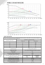
Page 8: ...i MAGI 2 Czynnik pompowany woda pozbawiona gazu Gęstość wody dla której tworzono krzywe wynosiła ρ 983 2 kg m3 a temperatura 60 C Wszystkie wartości wyrażone krzywymi są średnimi nie mogą być traktowane jako gwarantowane krzywe Jeśli wymagana jest pewna wydajność należy przeprowadzić pomiar osobno dla danego egzemplarza pompy Krzywe tworzono przy lepkości kinematycznej pompowanej wody υ 0 474 mm2 ...

Page 9: ...silnika Nie ma potrzeby dodatkowego zabezpieczenia silnika Stopień ochrony IP 44 Klasa izolacji Maksymalna wilgotność względna otoczenia Maksymalne ciśnienie w układzie CO Minimalne ciśnienie napływu na ssaniu w zależności od temperatury czynnika grzewczego Ciśnienie akustyczne pracującej pompy Dopuszczalna temperatura otoczenia Maksymalna temp czynnika grzewczego Maksymalne nagrzanie powierzchni ...

Page 10: ...urządzeniejestwłaściwego rodzaju i pełni tę samą funkcję co nowo zakupione urządzenie Zabronione jest wyrzucanie zużytego sprzętu elektrycznegowrazzinnymiodpadkamipowstającymiwgospodarstwachdomowych KONSERWACJA UTYLIZACJA DEKLARACJA ZGODNOŚCI DEKLARACJA ZGODNOŚCI UE WE Moduł A 1 POMPY OBIEGOWE MAGI 2 MAGI 2 25 40 180 MAGI 2 25 60 180 MAGI 2 25 60 130 2 PHU Dambat Gawartowa Wola 38 05 085 KAMPINOS ...

Page 11: ... wpisami w karcie gwarancyjnej a dokumentem zakupu 8 Gwarancja obejmuje tylko urządzenia eksploatowane na terenie RP 9 W przypadku wysyłki urządzenia do naprawy przez użytkownika przy wysyłkach urządzeń między innymi o wadze powyżej 20 kg gwarant pokrywa koszty transportu do serwisu Przed wysyłką proszę skontaktować się z gwarantem w celu uzyskania informacji którą firmą kurierską wysłać urządzenie...

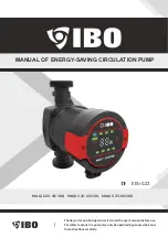
Page 12: ...ION PUMP MAGI 2 25 40 180 MAGI 2 25 60 130 MAGI 2 25 60 180 EEI 0 23 Thank you for purchasing our device read the user s manual before use For safety reasons the pump may only be operated by people who know the instructions carefully ...

Page 13: ... been installed does not work and the ambient temperature is below 0 C discharge water from the heating system Please bear in mind that freezing water can burst the pump body 14 If the pump does not operate for a long time close the ball valves cutting off the pump and cut off electric power supply 15 If the electric wire powering the pump is damaged refer to an authorised servicing team to replac...

Page 14: ...ise level of the pump and the entire system Low power consumption Compared to the traditional circulation pump power consumption of the MAGI 2 series pump is very low and can reach even 5W depending on the system The MAGI series circulation pump is equipped with a motor with permanent magnets and pressure difference regulator which constantly and automatically adapt the pump efficiency to meet the...

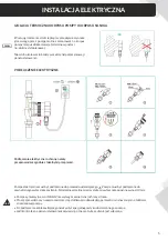
Page 15: ... following activities 1 Disconnect the pump from power supply 2 Close the cut off valves at the inflow and outflow of the pump and perform decompression 3 Loosen and remove four bolts fixing the head in the pump body 4 Rotate the motor into the desired position and fit four openings for bolts 5 Insert four ampoule head screws to proper sockets and tighten them WARNING The heating medium can have high ...

Page 16: ...mple a Styrofoam lining Do not insulate or cover the junction box or the control panel ELECTRIC CONNECTION The electric connection and protection must follow the local regulations The electric pump must be connected to an earthing conductor The pump must be connected to the external power supply breaker The minimum slit between the pins of the breaker must be 3 mm USE AND CARE GUIDE MAGI 2 ...
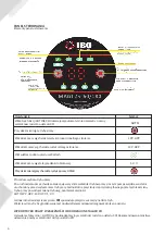
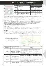
Page 17: ... acc to constant rotary speed Changing mode button 40 60 Displayed error codes After the power supply is switched on all of dispays will flesh on after which the pump will enter the last running mode before it is switched off Pressing the main switch button once changes the mode by the following order For example if the pump is operating in CP1 mode pressing the button once will cause switching to ...

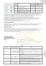
Page 18: ...he seal on it DEPENDENCY BETWEEN PUMP SETTINGS AND ITS OPERATING PARAMETERS Ustawienie AUTO factory settings Krzywa charakterystyki pracy pompy Funkcja From the highest to the lowest curve of proportionate pressure characteristics Curves of proportionate pressure Curves of constant pressure The AUTO function controls the pump efficiency automatically in the specified range It adjusts the pump efficie...

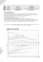
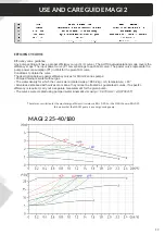
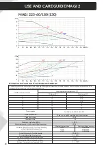
Page 19: ...2 series pumps Pumped medium water without gas The water density for which the curves were created was ρ 983 2 kg m3 temperature 60 All values expressed with curves are means they cannot be treated as guaranteed curves If a specific efficiency is required carry out a separate measurement for the given pump The curves were created using pumped water kinematic viscosity υ 0 474 mm2 s 0 474CcST The ref...

Page 20: ...ion There is no need for additional motor protection Protection rating IP 44 Insulation class Maximum relative humidity Maximum pressure in the central heating system Minimum inflow pressure at suction depending on heating medium temperature Acoustic pressure of working pump Permissible ambient temperature Maximum heating medium temperature Maximum heating up of pump surface Range of temperatures o...

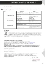
Page 21: ...ase the inflow pressure at the pump inlet Loud pump operation Air in the pump Vent it Inflow pressure too low cavitation Increase the inflow pressure at the inlet to the pump Pump parameters too low If possible increase the pump operation mode into a more efficient one otherwise install stronger pump Gawartowa Wola 23 11 2018 Adam Jastrzębski EC DECLARATION OF CONFORMITY Moduł A 1 Circulating pumps MA...

Page 22: ...5 60 180 EEI 0 23 BETRIEBSANLEITUNG DER ENERGIESPARENDEN UMWÄLZPUMPE ACHTUNG Lesen Sie vor Gebrauch die Bedienungsanleitung Aus Sicherheitsgründen sind für die Pumpensteuerung nur Personen zugelassen die die Bedienungsanleitung gründlich kennen ...

Page 23: ...installiert ist gut belüftet ist Es hilft Feuchtigkeitskondensation zu vermeiden die einen elektrischen Fehler verursachen kann 13 Wenn im Winter das Zentralheizungssystem in dem die Pumpe installiert ist nicht funktioniert und die Umgebungstemperatur unter 0 C liegt entleeren Sie das Heizungs und Wassersystem Beachten Sie dass bei gefrierendem Wasser die Pumpe platzen kann 14 Wenn die Pumpe länge...

Page 24: ...ale Systemdruck beträgt 1 0 MPa 10 Bar Schutzart IP44 Druck der in die Pumpe eintritt Die Umwälzpumpe der MAGI 2 Serie ist mit einem Permanentmagnetmotor und einem Differenzdruckregler ausgestattet der die Pumpenleistung automatisch und kontinuierlich an den tatsächlichen Bedarf der Anlage anpasst Die Umwälzpumpe der MAGI 2 Serie ist mit einem Bedienfeld auf der Oberseite des Motors ausgestattet d...

Page 25: ... die Absperrkugelventile am Pumpeneinlass und auslass und entlasten Sie den Druck 3 Lösen und entfernen Sie die vier Schrauben mit denen der Pumpenkopf am Pumpengehäuse befestigt ist 4 Drehen Sie den Motor in die gewünschte Position und richten Sie die vier Schraubenlöcher aus 5 Stecken Sie die vier Innensechskantschrauben in die entsprechenden Löcher und ziehen Sie sie fest WARNUNG Das Heizmedium...

Page 26: ...ß den örtlichen Vorschriften ausgeführt werden Die Elektropumpe muss an den Schutzleiter I angeschlossen werden Die Pumpe muss an einen externen Netzschalter angeschlossen werden Der Mindestabstand zwischen den Schaltkontakten sollte 3 mm betragen Die Umwälzpumpe der MAGI 2 Serie benötigt keinen externen Motorschutz Bitte überprüfen Sie ob die Versorgungsspannung und frequenz mit denen auf dem Typ...

Page 27: ...sweise zur Auswahl der Betriebsart Nach dem Start leuchten kurz alle Betriebsmodusanzeigen auf dann geht die Pumpe in den letzten Betriebsmodus vor dem Ausschalten Einmaliges Drücken der Haupttaste des Betriebsmodus Umschalters bewirkt den Wechsel der Betriebsart in der folgenden Reihenfolge AUTO LPP HPP LCP HCP 1 2 3 Durch einmaliges Drücken der Taste gelangen Sie zum nächsten Modus in der Liste ...

Page 28: ...Einstellung Kennlinie des Pumpenbetriebs Funktion AUTO Werkseinstellung Proportionaldruck Kennlinie von hohem zu niedrigem Druck Die AUTO Funktion regelt automatisch die Pumpenleistung innerhalb eines bestimmten Bereichs Passt die Pumpenleistung je nach Anlagengröße an Passt die Pumpenleistung entsprechend der Laständerung über einen bestimmten Zeitraum an Im AUTO Modus befindet sich die Pumpe im ...

Page 29: ...istungskurve stellt die Pumpenleistungsaufnahme P1 in Watt bei einer gegebenen Q H Kurve dar 10 2 Bedingungen zum Erhalt der Kurve Die folgende Beschreibung gilt für die Leistungskurven der Pumpen der MAGI 2 Serie Fördermedium gasfreies Wasser Die Wasserdichte für die die Kurven erstellt wurden betrug p 983 2 kg m und die Temperatur 60 C Alle in Kurven ausgedrückten Werte sind Durchschnittswerte u...

Page 30: ...z Ein zusätzlicher Motorschutz ist nicht erforderlich Schutzart IP 44 Isolationsklasse H Maximale relative Luftfeuchtigkeit der Umgebung 95 Höchstdruck im Zentralheizungssystem 1 MPa Mindesteingangsdruck an der Saugseite abhängig von der Temperatur des Heizmediums Temperatur des Heizmediums Min Eingangsdruck 85 C 90 C 110 C 0 005 MPa 0 028 MPa 1 000 MPa Schalldruck einer laufenden Pumpe 43 dB A Zu...

Page 31: ...nge das zurückgegebene Gerät vom richtigen Typ und vollständig ist und die gleiche Funktion wie das neu gekaufte Gerät erfüllt Es ist verboten gebrauchte Elektrogeräte zusammen mit anderem Hausmüll zu entsorgen Jahr der Kennzeichnung des Gerätes ist das CE Zeichen vom Händler anhand des Typenschildes einzutragen KONFORMITÄTSERKLÄRUNG Jahr der Kennzeichnung des Gerätes ist das CE Zeichen vom Händle...

Reviews: