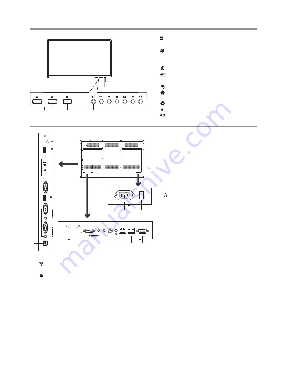
1. : USB
standard
interface of the IFP
,
enable
connection
to
USB2.0 standard
devices
.
2. : USB
standard
interface of the OPS
,
enable
connection
to
USB2.0 standard
devices
.
Note:
If no OPS, the USB port has no function.
3.
:
Switch the IFP power on or standby.
4. : Press the button to display input source menu
or exit the menu screen.
5. : Press the button to return to previous menu
.
6
.
: Press the button to display desktop (Home
page) on the screen
.
7
.
: Press the button to open the setting menu
.
8. : Press the button to turn down the volume
.
9. : Press the button to turn up the volume
.
Remote Sensor
Power Indicator
Identification of Controls
5
AC IN
13
14
2
1
3
4
5
6
HDMI 1
HDMI 2
HDMI 3
USB
USB 3.0
VGA
OUT
VGA
VGA
AUDIO
P
C
IN
1
AUDIO
P
C
IN
2
TOUCH
OUT
5
7 8 9 10 11
12
AV IN
SPDIF
LAN OUT
RS-232
VGA
WAN IN
AUDIO
PC IN 3
1.
WIFI port for transmitting or receiving network signal.
2. USB2.0/3.0
USB
standard
interface
,
enable
connection
to
USB2.0, USB3.0 standard
devices
.
When connecting,
please select the appropriate port.
3.HDMI1/2/3 Input
To connect with those equipments with HDMI or DVI
interface, for example, Set-top box or DVD player. (A
HDMI-to-DVI adapter cable is required when you are
connecting a DVI-equipped device to the IFP.)
4.VGA OUT
The currently selected PC IN 1/2/3 signal output.
2
5.PC IN1/2/3
Enable connection to PC or other external devices
with VGA/AUDIO ports.
6.TOUCH OUT
Control the external devices by native touch
control (For example computer). (Only for
PC1/2/3
、
HDMI1 signal.)
7.AV IN
Connect an AV device to this jack.
8.S/PDIF digital audio output
Connect a digital sound system to this jack.
9.
Connect headphones to this jack. IFP is the
current audio output.
10.LAN OUT
The built-in router output port. Connection to
another computer or other Internet enabled
devices.
11.WAN IN
The built-in router input port. Connect to the
external network.
12.RS232
For service, software upgrades and the other
uses.
13. AC IN
Plug the AC cord into this jack and into a power
outlet.(~100-240V 50Hz/60Hz
)
14. Power Switch
Push to (1) to connect the power, push to (O ) to
cut off.
Note
:
Power switch can not be covered, and should
keep the power switch can be conveniently
operated.
1
2
3 4
5
6
7 8
9
Summary of Contents for LTE55-003V+
Page 24: ...PRINTED ON RECYCLED PAPER ...


