
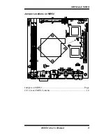


INSTALLATIONS
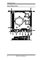
J16: PCI-E X16 slot (X8 LINK)
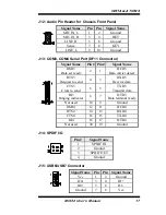
J17: Front Panel
Signal Name
Pin #
Pin #
Signal Name
Power BTN
1
2
Power BTN
HDD LED
3
4
HDD LED
Reset BTN
5
6
Reset BTN
Power LED
7
8
Power LED
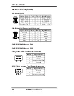
J18: Digital I/O Connector (4 in, 4 out)
Signal Name
Pin #
Pin #
Signal Name
Ground 1 2 +5V
Out3 3
4 Out1
Out2 5
6 Out0
IN3 7
8 IN1
IN2 9
10 IN0
J5: DDR II DIMM Socket CHA
J3: DDR II DIMM Socket CHB
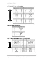
CPU_FAN1: CPU Fan Power Connector
Pin #
Signal Name
1 Ground
2 +12V
3 Rotation
detection
4 Control
SYS_FAN1: system Fan1 Power Connector
Pin #
Signal Name
1 Ground
2 +12V
3 Rotation
detection
18
MI952 User’s Manual


