background image

APPENDIX 

42


MI952 User’s Manual


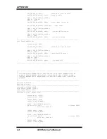
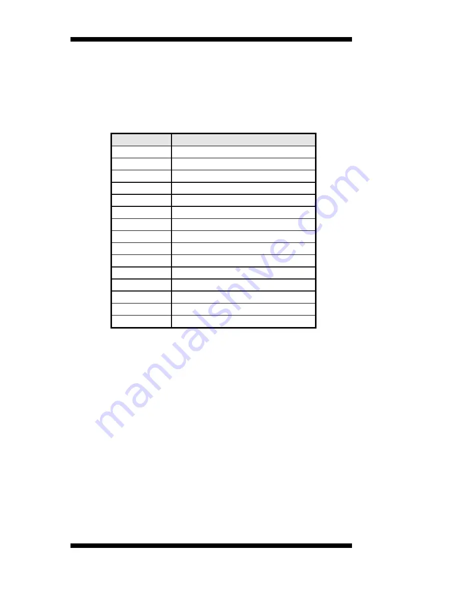
B. Interrupt Request Lines (IRQ) 

 
Peripheral devices use interrupt request lines to notify CPU for the 
service required. The following table shows the IRQ used by the devices 
on board. 


Level 

Function 

IRQ0 

System Timer Output 

IRQ1 Keyboard 
IRQ2 Interrupt 

Cascade 

IRQ3 

Serial Port #2, 4 

IRQ4 

Serial Port #1, 3 

IRQ5 Reserved 
IRQ6 Reserved 
IRQ8 

Real Time Clock 

IRQ9 Reserved 
IRQ10 Reserved 
IRQ11 Reserved 
IRQ12 PS/2 

Mouse 

IRQ13 80287 
IRQ14 Primary 

IDE 

IRQ15 Secondary 

IDE 


Summary of Contents for MI952

Page 1: ...MI952 AMD Athlon 64 Athlon 64 x2 Dual Core Sempron Mini ITX Motherboard USER S MANUAL Version 1 0 ...

Page 2: ...usiness Machines Corporation AMD Athlon 64 Athlon 64 x2 dual core Sempron processors are registered trademarks of AMD Corporation Microsoft Windows is a registered trademark of Microsoft Corporation Winbond is a registered trademark of Winbond Electronics Corporation All other product names or trademarks are properties of their respective owners ...

Page 3: ... MI952 Specifications 3 Board Dimensions 4 Installations 5 Installing the CPU 6 Installing the Memory 7 Setting the Jumpers 8 Connectors on MI952 11 BIOS Setup 19 Drivers Installation 35 Appendix 41 A I O Port Address Map 41 B Interrupt Request Lines IRQ 42 C Watchdog Timer Configuration 45 ...

Page 4: ...iv MI952 User s Manual This page is intentionally left blank ...

Page 5: ... a maximum memory capacity of 4GB Particular attention is given to multiple high resolution display interfaces including a DVI I DVI D and an HDMI connector at the edge of the board MI952 Product Features With AMD 780E SB710 Chipset Supports Socket AM2 CPUs AMD Athlon 64 Athlon 64 x2 dual core Sempron Supports up to 2 9GHz FSB 2000MHz DVI D DV I HDMI multiple display interface Dual PCIe Gigabit LA...

Page 6: ...ser s Manual Checklist Your MI952 package should include the items listed below The MI952 Mini ITX motherboard This User s Manual 1 CD containing chipset drivers and flash memory utility Cable kit USB Serial port Serial ATA ...

Page 7: ...t controller support 8 ports 6 x external ports 2 ports by pin headers Audio AMD SB710 built in audio controller HAD ALC888 w 7 1 channels Serial ATA 2 x SATA II connectors SB710 built in SATA II Controller IDE None LPC I O FINTEK F81865 4 x COM Hardware monitor 2 x FAN connector RTC CMOS SB710 built in with on board Lithium Battery Edge Connector 1 x DVI D DVI I connectors stack 4 x USB connector...

Page 8: ...INTRODUCTION Board Dimensions 4 MI952 User s Manual ...

Page 9: ...ations This section provides information on how to use the jumpers and connectors on the MI952 in order to set up a workable system The topics covered are Installing the CPU 6 Installing the Memory 7 Setting the Jumpers 8 Connectors on MI952 11 ...

Page 10: ...le as shown below Then position the CPU above the socket such that the CPU corner aligns with the gold triangle matching the socket corner with a small triangle Carefully insert the CPU into the socket and push down the lever to secure the CPU Then install the heat sink and fan NOTE Ensure that the CPU heat sink and the CPU top surface are in total contact to avoid CPU overheating problem that wou...

Page 11: ...t on the board and perform the following steps 1 Hold the DDR2 module so that the key of the DDR2 module aligned with that on the memory slot 2 Gently push the DDR2 module in an upright position until the clips of the slot close to hold the DDR2 module in place when the DDR2 module touches the bottom of the slot 3 To remove the DDR2 module press the clips with both hands DDR2 Module Lock Lock Lock...

Page 12: ...ect various settings and features according to your needs and applications Contact your supplier if you have doubts about the best configuration for your needs The following lists the connectors on MI952 and their respective functions Jumper Locations on MI952 9 JU5 Clear CMOS Contents 10 ...

Page 13: ...INSTALLATIONS Jumper Locations on MI952 Jumpers on MI952 Page JU5 Clear CMOS Contents 10 MI952 User s Manual 9 ...

Page 14: ...INSTALLATIONS JU5 Clear CMOS Contents JU5 Setting Function Pin 1 2 Short Closed Normal Pin 2 3 Short Closed Clear CMOS 10 MI952 User s Manual ...

Page 15: ...J1 External SPI flash connecter 15 J2 LPC Debug Port 15 J6 ATX 12V Power Connector 15 J7 24 pin ATX Power Connector 16 J9 J10 SATAII Connectors 16 J11 COM1 COM2 Serial Port DF11 Connector 16 J12 Audio Pin Header for Chassis Front Panel 17 J13 COM3 COM4 Serial Port DF11 Connector 17 J14 SPDIF I O 17 J15 USB6 USB7 Connector 17 J16 PCI E X16 slot X8 LINK 18 J17 Front Panel 18 J18 Digital I O Connecto...

Page 16: ... JU4 SPI Flash select 15 J1 External SPI flash connecter 15 J2 LPC Debug Port 15 J6 ATX 12V Power Connector 15 J7 24 pin ATX Power Connector 16 J9 J10 SATAII Connectors 16 J11 COM1 COM2 Serial Port DF11 Connector 16 J12 Audio Pin Header for Chassis Front Panel 17 J13 COM3 COM4 Serial Port DF11 Connector 17 J14 SPDIF I O 17 J15 USB6 USB7 Connector 17 J16 PCI E X16 slot X8 LINK 18 J17 Front Panel 18...

Page 17: ... N C SHIELD 1 3 11 C2 N C DATA 3 12 C3 N C DATA 3 13 C4 N C DDC POWER 14 C5 N C A GROUND 1 15 C6 N C Signal Name Pin Pin Signal Name DATA 2 1 16 HOT POWER DATA 2 2 17 DATA 0 Shield 2 4 3 18 DATA 0 DATA 4 4 19 SHIELD 0 5 DATA 4 5 20 DATA 5 DDC CLOCK 6 21 DATA 5 DDC DATA 7 22 SHIELD CLK VSYNC 8 23 CLOCK DATA 1 9 24 CLOCK DATA 1 10 C1 A RED SHIELD 1 3 11 C2 A GREEN DATA 3 12 C3 A BLUE DATA 3 13 C4 HY...

Page 18: ...a 2 Mouse data 3 Ground 4 Vcc 5 Keyboard Clock 6 Mouse Clock CN2 USB4 USB5 Connectors On top of the J8 HDMI connector are the stacked USB 4 and USB 5 ports J8 HDMI Connector Below two stacked USB connectors is the J8 HDMI connector CN3 Gigabit LAN RTL8111C RJ45 USB 2 3 CN4 Gigabit LAN RTL8111C RJ45 USB 0 1 CN5 HD Audio Connector 14 MI952 User s Manual ...

Page 19: ...Name Pin Pin Signal Name Key 1 2 NC CE 3 4 3 3VDUAL Data In 5 6 HOLD WP 7 8 CLK Ground 9 10 Data Out J2 LPC Debug Port Signal Name Pin Pin Signal Name LAD0 1 2 PCI RST LAD1 3 4 LFRAME LAD2 5 6 3 3V LAD3 7 8 Ground PCI CLK 9 10 Key J6 ATX 12V Power Connector This connector supplies the CPU operating voltage Pin Signal Name 1 Ground 2 Ground 3 12V 4 12V MI952 User s Manual 15 ...

Page 20: ...round 24 12 3 3V J9 J10 SATAII Connectors Pin Signal Name 1 Ground 2 TX 3 TX 4 Ground 5 RX 6 RX 7 Ground J11 COM1 COM2 Serial Port DF11 Connector Signal Name Pin Pin Signal Name Data set ready 2 1 Data carrier detect Request to send 4 3 Receive data Clear to send 6 5 Transmit data Ringing indicator 8 7 Data terminal ready Not used 10 9 Ground DSR2 12 11 DCD2 RTS2 14 13 RXD2 CTS2 16 15 TXD2 RI2 18 ...

Page 21: ...y 2 1 DCD3 Data carrier detect RTS3 Request to send 4 3 RXD3 Receive data CTS3 Clear to send 6 5 TXD3 Transmit data RI3 Ringing indicator 8 7 DTR3 Data terminal ready Not used 10 9 Ground DSR4 12 11 DCD4 RTS4 14 13 RXD4 CTS4 16 15 TXD4 RI4 18 17 DTR4 Not used 20 19 Ground J14 SPDIF I O Pin Signal Name 1 SPDIF IN 2 Ground 3 SPDIF OUT 4 Ground J15 USB6 USB7 Connector Signal Name Pin Pin Signal Name ...

Page 22: ...gital I O Connector 4 in 4 out Signal Name Pin Pin Signal Name Ground 1 2 5V Out3 3 4 Out1 Out2 5 6 Out0 IN3 7 8 IN1 IN2 9 10 IN0 J5 DDR II DIMM Socket CHA J3 DDR II DIMM Socket CHB CPU_FAN1 CPU Fan Power Connector Pin Signal Name 1 Ground 2 12V 3 Rotation detection 4 Control SYS_FAN1 system Fan1 Power Connector Pin Signal Name 1 Ground 2 12V 3 Rotation detection 18 MI952 User s Manual ...

Page 23: ...are as follows BIOS Introduction 20 BIOS Setup 20 Standard CMOS Setup 22 Advanced BIOS Features 24 Advanced Chipset Features 27 Integrated Peripherals 26 Power Management Setup 30 PNP PCI Configurations 31 PC Health Status 32 Frequency Voltage Control 33 Load Fail Safe Defaults 34 Load Optimized Defaults 34 Set Supervisor User Password 34 Save Exit Setup 34 Exit Without Saving 34 ...

Page 24: ...mediately activated Pressing the Del key immediately allows you to enter the Setup utility If you are a little bit late pressing the Del key POST Power On Self Test will continue with its test routines thus preventing you from invoking the Setup If you still wish to enter Setup restart the system by pressing the Reset button or simultaneously pressing the Ctrl Alt and Delete keys You can also rest...

Page 25: ...displays the control keys for this menu At the bottom of the Main Menu just below the control keys section there is another section which displays information on the currently highlighted item in the list Note If the system cannot boot after making and saving system changes with Setup the Award BIOS supports an override to the CMOS settings that resets your system to its default Warning It is stro...

Page 26: ...pr 28 2007 Item Help Time hh mm ss 00 00 00 Menu Level IDE Channel 0 Master None IDE Channel 0 Slave None IDE Channel 2 Master None IDE Channel 2 Slave None IDE Channel 3 Master None IDE Channel 3 Slave None Change the day month Year and century Halt On All but keyboard Base Memory 640K Extended Memory 129024K Total Memory 130048K At the bottom of the menu are the control keys for use on this menu...

Page 27: ... Number of cylinders HEAD Number of read write heads PRECOMP Write precompensation LANDING ZONE Landing zone SECTOR Number of sectors Remarks The main board supports two serial ATA ports and are represented in this setting as IDE Channel 0 Halt On This field determines whether or not the system will halt if an error is detected during power up No errors The system boot will not be halted for any e...

Page 28: ...elect For DRAM 64MB Non OS2 HDD S M A R T Capability Disabled CPU Feature Press Enter to configure the settings relevant to CPU Feature Hard Disk Boot Priority With the field there is the option to choose aside from the hard disks connected Bootable add in Cards which refers to other external devices Virus Warning If this option is enabled an alarm message will be displayed when trying to write on...

Page 29: ...t Up NumLock Status This allows you to activate the NumLock function after you power up the system Gate A20 Option This field allows you to select how Gate A20 is worked Gate A20 is a device used to address memory above 1 MB Typematic Rate Setting When disabled continually holding down a key on your keyboard will generate only one instance When enabled you can set the two typematic controls listed...

Page 30: ...e Interrupt Controller The default setting is Enabled MPS Version Control for OS This option is specifies the MPS Multiprocessor Specification version for your operating system MPS version 1 4 added extended configuration tables to improve support for multiple PCI bus configurations and improve future expandability The default setting is 1 4 OS Select for DRAM 64MB This option allows the system to...

Page 31: ...features settings for Primary Dual Slot Config GPP Slots Power Limit GFX ports GPPs and NB SB port features Internal Graphics Mode There are two different setting selections for MI952 and MI952F The settings for MI952 are Disabled and UMA while the MI952F has additional settings of Sideport and UMA sideport Init Display First The default setting is IGX NB Power Management The default setting is Au...

Page 32: ...al Port 1 3F8 IRQ4 Onboard Serial Port 2 2F8 IRQ3 Onboard Serial Port 3 3E8 IRQ4 Onboard Serial Port 4 2F8 IRQ3 PWRON after PWR Fail OFF USB Device Setting Press Enter Phoenix AwardBIOS CMOS Setup Utility Onboard Devices Onboard Realtek NIC Enabled ITEM HELP Onboard Lan Boot ROM Disabled Menu Level Phoenix AwardBIOS CMOS Setup Utility OnChip SATA Device OnChip SATA Controller Enabled OnChip SATA T...

Page 33: ...ial ports and their addresses The default values for these ports are Serial Port 1 3F8 IRQ4 Serial Port 2 2F8 IRQ3 Serial Port 3 3E8 IRQ4 Serial Port 4 2E8 IRQ3 PWRON After PWR Fail This field sets the system power status whether on or off when power returns to the system from a power failure situation ...

Page 34: ... defines the power off mode when using an ATX power supply The Instant Off mode allows powering off immediately upon pressing the power button In the By Hardware mode the system powers off when the power button is pressed for more than four seconds or enters the suspend mode when pressed for less than 4 seconds HPET Support HPET or High Precision Event Timer formerly known as Multimedia Timer is a...

Page 35: ...e configuration data or not The default value is Disabled Resources Controlled by This PnP BIOS can configure all of the boot and compatible devices with the use of a PnP operating system such as Windows 95 PCI VGA Palette Snoop Some non standard VGA display cards may not show colors properly This field allows you to set whether or not MPEG ISA VESA VGA cards can work with PCI VGA When this field ...

Page 36: ... 30 o C 86 o F SYS Smart Fan Auto Mode Sys Fan Temp 30 o C 86 o F Shutdown Temperature This field allows the user to set the temperature by which the system automatically shuts down once the threshold temperature is reached This function can help prevent damage to the system that is caused by overheating Temperatures Voltages These fields are the parameters of the hardware monitoring function feat...

Page 37: ... Control Phoenix AwardBIOS CMOS Setup Utility Frequency Voltage Control Spread Spectrum Disabled ITEM HELP Menu Level Spread Spectrum This field sets the value of the spread spectrum The default setting is Disabled This field is for CE testing use only ...

Page 38: ...ssword message prompts on the screen Type the password up to eight characters in length and press Enter The system confirms your password by asking you to type it again After setting a password the screen automatically returns to the main screen To disable a password just press the Enter key when you are prompted to enter the password A message will confirm the password to be disabled Once the pas...

Page 39: ...der the Windows 2000 and Windows XP The software and drivers are included with the motherboard If you find the items missing please contact the vendor where you made the purchase The contents of this section include the following VGA Drivers Installation 36 Realtek High Definition Codec Audio Driver Installation 38 LAN Drivers Installation 39 ...

Page 40: ...allation 1 Insert the CD that comes with the board Click AMD and click AMD 780E Series Graphics Drivers 2 In the Welcome screen click Next to continue Then in the License Agreement screen also click Yes to continue 36 MI952 User s Manual ...

Page 41: ...Express Recommended in selecting the component that you want to install 4 When the message regarding Windows Logo testing appears click Continue Anyway to proceed with the driver installation Setup is now complete Click Finish to restart the computer MI952 User s Manual 37 ...

Page 42: ...on 1 Insert the CD that comes with the board Click AMD and click Realtek High Definition Codec Audio Driver 2 In the Welcome screen click Next to continue After the driver installation is complete click Finish on the next screen to restart the computer 38 MI952 User s Manual ...

Page 43: ...s Installation 1 Insert the driver CD that comes with the board Click AMD and click Realtek GbE_FE Ethernet PCI E NIC Driver 2 When the Welcome screen of the InstallShield Wizard appears click Next to continue MI952 User s Manual 39 ...

Page 44: ...ION 3 On the next screen you are asked to click Install to begin the installtion process Now click Install to proceed 4 Installation is now complete click Finish to exit the InstallShield Wizard 40 MI952 User s Manual ...

Page 45: ...oller 1 020h 03Fh Interrupt Controller 1 040h 05Fh Timer 060h 06Fh Keyboard Controller 070h 07Fh Real Time Clock NMI 080h 09Fh DMA Page Register 0A0h 0BFh Interrupt Controller 2 0C0h 0DFh DMA Controller 2 0F0h Clear Math Coprocessor Busy Signal 0F1h Reset Math Coprocessor 1F0h 1F7h IDE Interface 2E8h 2FFh Serial Port 4 COM4 2F8h 2FFh Serial Port 2 COM2 2B0 2DF Graphics adapter Controller 3C0 3CF E...

Page 46: ...red The following table shows the IRQ used by the devices on board Level Function IRQ0 System Timer Output IRQ1 Keyboard IRQ2 Interrupt Cascade IRQ3 Serial Port 2 4 IRQ4 Serial Port 1 3 IRQ5 Reserved IRQ6 Reserved IRQ8 Real Time Clock IRQ9 Reserved IRQ10 Reserved IRQ11 Reserved IRQ12 PS 2 Mouse IRQ13 80287 IRQ14 Primary IDE IRQ15 Secondary IDE ...

Page 47: ... IMPLIED INCLUDING BUT NOT LIMITED TO THE IMPLIED WARRANTIES OF MERCHANTABILITY AND OR FITNESS FOR A PARTICULAR PURPOSE include dos h include conio h include stdio h include stdlib h include F81865 H int main int argc char argv void EnableWDT int void DisableWDT void int main int argc char argv unsigned char bBuf unsigned char bTime char endptr char SIO printf Fintek 81865 watch dog program n SIO ...

Page 48: ...bBuf disable WDTO output bBuf Get_F81865_Reg 0xF5 bBuf 0x20 bBuf 0x40 Set_F81865_Reg 0xF5 bBuf disable WDT THIS CODE AND INFORMATION IS PROVIDED AS IS WITHOUT WARRANTY OF ANY KIND EITHER EXPRESSED OR IMPLIED INCLUDING BUT NOT LIMITED TO THE IMPLIED WARRANTIES OF MERCHANTABILITY AND OR FITNESS FOR A PARTICULAR PURPOSE include F81865 H include dos h unsigned int F81865_BASE void Unlock_F81865 void v...

Page 49: ...81865_Reg unsigned char REG unsigned char Result Unlock_F81865 outportb F81865_INDEX_PORT REG Result inportb F81865_DATA_PORT Lock_F81865 return Result THIS CODE AND INFORMATION IS PROVIDED AS IS WITHOUT WARRANTY OF ANY KIND EITHER EXPRESSED OR IMPLIED INCLUDING BUT NOT LIMITED TO THE IMPLIED WARRANTIES OF MERCHANTABILITY AND OR FITNESS FOR A PARTICULAR PURPOSE ifndef __F81865_H define __F81865_H ...

Reviews: