VEHICLE
BATTERY
(+)12 volt power
30 AMP FUSE
+
VEHICLE
BATTERY
(+)12 volt power
30 AMP FUSE
+
Service/Program
Switch
BROWN
IGNITION
#2 OUTPUT
ACCESSORIES, HEATER,
AIR CONDITIONER 12V (+)
STARTER (+)
VIOLET
ORANGE
RED
RED
YELLOW
IGNITION #1 OUTPUT
Remote
Start
Receiver
Module
TEN PIN CONNECTOR
BROWN
RED
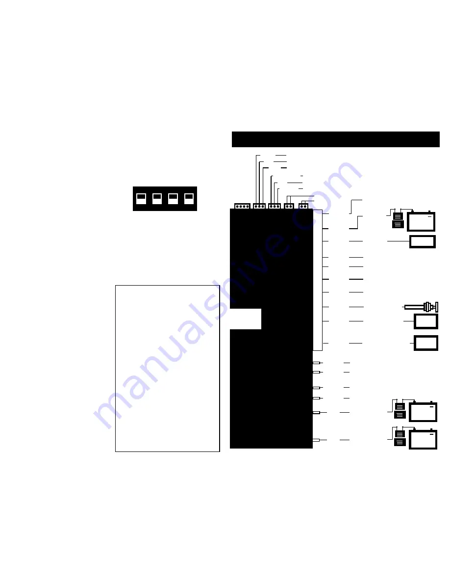
WIRING DIAGRAM
GRAY
(–) grounded output
For OE security system
For spark plug wire
or tach sensing
(–) output
for sensor trigger wir
e.
(–) output
to alarm
sensor output wir
e.
ORANGE
GREEN
RED
BLUE
WHITE
To door lock (–) pu
lse
(Optional relay’s may be required. Not included.)
See Relay Installation Sheet
Do not u
se
LED
To door unlock (–) pulse
(Optional relay’s may be required. Not included.)
See Relay Installation Sheet
White
Jack
Antenna
Jack
Red
Jack
Red
Jack
Blue
Jack
BRAKE
PEDAL
GREEN
BLUE
VIOLET
YELLOW
GREEN/BLACK
RED
YELLOW
To power trunk release
(Optional relay may be required. Not included.)
See Relay Installation Sheet
Factory alarm disarm
(Optional relay required. Not included.)
See Relay Installation Sheet
For optional vacuum switch sensing
(Optional vacuum switch may be required. Not included.)
SENSOR
VEHICLE
BATTERY
(Optional, See Installation Instructions)
(–) input from alarm 2nd channel
(Optional, See Installation Instructions)
(+) trigger input
From
brake light switch wire
(+)12 volt
power
(–) trigger input
From hood pin switch,
(–) TO GROUND
(+) 12 Volts when brake pedal depressed
BLACK
(Optional, See Installation Instructions)
Two pin blue connector:
This is for the
service/program switch. Mount this switch
near the drivers side and in a hidden loca-
tion under the dash. It should be accessi-
ble for use.
6) REMOTE PROGRAMMABLE FEATURES:
The remote starter has four programmable
features:
#1 - 2nd ignition relay on/off
On = used for 2nd ignition output.
Off = used for 2nd accessory output
#2 - Engine run time
On = 12 minutes
Off = 24 minutes
#3 - Door lock pulse time
On = .75 seconds
Off = 3 seconds
#4 - Double unlock pulse
On = single unlock pulse
Off = double unlock pulse
How to enter into the program mode:
1) Turn the ignition key to the on position.
2) Within ten seconds press the
service/program switch five times. The
parking lights and the dash mount LED will
flash three times. The system is now in pro-
gram mode.
How to program a feature:
1) Press the service/program switch the
same number of times as the feature num-
ber above. Once is for feature #1 2nd igni-
tion relay on/off, twice is for #2 engine run
time, etc. The parking lights and dash
mount LED will flash each time the switch
is pushed to confirm.
2) Press button #1 on one of the remote
transmitters to turn the feature to the ”on”
position. The parking lights and dash
mount LED will flash one time to confirm.
3) Press button #2 on one of the remote
transmitters to turn the feature to the ”off“
position. The parking lights and dash
mount LED will flash twice to confirm.
4) The system will automatically exit from
the program mode.
7) DIP SWITCHES:
There are four individual dip switches,
each controlling a specific function. The
switch should be left in the “on” position if
it is not being used. To use the function,
put the dip switch in the “off” position
#1:
Is used for the tach or sparkplug wire
sensing hook up. Put this switch in the “off”
position.
#2:
Is used for the optional vacuum switch.
Put this switch in the “off” position if you are
using the optional vacuum switch.
#3:
Is used to increase the starter crank
time. To increase the crank time put the
switch in the “off” position.
#4:
Is used if the vehicle has a diesel
engine. If the vehicle has a diesel engine,
put this switch in the “off” position.
ON
OFF
1
2
3
4
INSTALLATION INSTRUCTIONS CONTINUED
ENTIRE INSTRUCTIONS SHOULD BE READ BEFORE BEGINNING INSTALLATION.
DIP
SWITCHES
Remove cover
to set.
See installation
instructions.
HOOD PIN SWITCH
30 AMP FUSE
ALARM
SYSTEM
122706
+
(+) output To parking light wire
that supplies (+) 12 volt power
4
5
POSSIBLE REMEDY
Check power and
ground connection.
Try to reprogram
remote back into
module.
Check connection
to starter wire.
Check tach wire
connection.
Check for factory
security system
Check for 2nd
ignition
Check to see if unit is
in service mode
Check to see if unit is
in auto cold start
mode
Check to see if switch
#3 is in
off position
TROUBLE SHOOTING
PROBLEM
Unit will not
respond to
remotes
Vehicle will not
crank
Vehicle starts,
then shuts down
Vehicle starts
but check engine
light comes on
Keyless entry
works but will
not remote start.
LED light solid red.
Vehicle is starting
on its own.
Vehicle will not
stay running,
needs longer
crank time.
ON DIP


