

5
Installation Instructions
BEFORE YOU BEGIN
This system is compatible with electronic
fuel injected engines only! Not intended
for use with carbureted engines.
• This product must be installed by qualified
personnel according to these instructions
and observing all safety features.
• Check to see if the vehicle is equipped
with any type of factory security system.
• Check to see if there is a pin switch for the
hood, if not one must be installed.
• Verify that the vehicle starts and idles
properly before beginning the installation.
• Always use a multi-meter to verify wiring.
• Before mounting the product, verify with
the customer the desired location for the
window mount receiver.
MOUNTING COMPONENTS
Mount the start module under the dash
where it will be away from moving parts such
as brake pedals, etc. Mount the receiver to
the inside of the windshield using the supplied
double-sided tape. Make sure the chosen
location does not obscure the driver’s view.
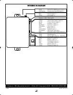
MODULE WIRING
6-Pin Starter Harness
• YELLOW WIRE - Start output (+). Con-
nect to the vehicle’s starter wire.
• GREEN WIRE - Main accessory output (+).
12V output for heater and/or air condition-
ing system. For cars with more than one
accessory wire add a relay(s) to power the
extra accessory wire(s) or if the WHITE
wire is not being used, it can be programmed
for second accessory output. See
Program-
mable Features.
• RED WIRE - Main power input A (+). Using
the supplied in-line fuse holder, connect to
the vehicle’s battery or alternate power
source with a minimum 30 Amp supply.
• RED WIRE - Main power input B (+). Using
the supplied in-line fuse holder, connect to
the vehicle’s battery or alternate power
source with a minimum 30 Amp supply.
• WHITE WIRE - Second ignition output (+).
Connect to the wire that sw12V and
does not drop out during cranking. This wire
may be optionally set via jumper for use as a
second accessory wire or second starter
wire. See
Programmable Features.
• BLUE WIRE - Main ignition output (+).
Connect to the main ignition wire that
sw12V without drop during crank.
2-Pin Connector
• BLACK WIRE - Ground input (-). Connect
to a chassis ground free of paint or dirt.
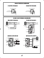
• WHITE WIRE - Parking Light output (+/-)
10A relay. Connect to the vehicle’s parking
light wire. If the vehicle is equipped with
more than four parking lights or with inde-
pendent left and right parking light circuits a
relay is required. For vehicles with negative
trigger parking lights, move the polarity
jumper inside the module to negative.
NOTE: Do not connect the parking light out-
put to the vehicle’s headlight circuit.
9-Pin Main Harness
• YELLOW WIRE - Factory Alarm Arm out-
put (-) 250mA. Connect to the wire that
requires a ground pulse to arm the factory
alarm. The YELLOW wire provides a ground
pulse when the remote transmitter is used
to lock the doors or when the remote start
shuts down. See
Programmable Features
RS160manualRev3:BW2450.qxd 1/7/2010 2:24 PM Page 5
Summary of Contents for RS160
Page 14: ...14 NOTES ...