6
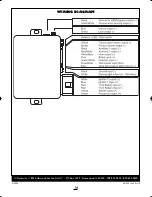
• BROWN WIRE - Factory Alarm Disarm
output (-) 250mA. Connect to the wire that
requires a ground pulse to disarm the fac-
tory alarm. The BROWN wire provides a
ground pulse when the remote transmitter is
used to unlock the doors and prior to
remote start activation.
• BLACK WIRE - Auxiliary 1 / Trunk Release
output (-) 250mA. Connect to a relay for an
optional feature such as trunk release. The
BLACK wire can instead be programmed for
use as a negative Accessory or Starter out-
put if needed. When programmed for Acces-
sory or Starter output, transmitter button 3
activates the Car Finder Feature. See
Pro-
grammable Features
• RED/WHITE WIRE - Auxiliary 2 output (-)
250mA. Connect to a relay for an optional
feature. The RED/WHITE wire can instead
be programmed for use as a Dome Light out-
put or Passenger Unlock output. See
Pro-
grammable Features
• WHITE/BLUE WIRE - Horn output (-)
250mA. Connect to an optional relay to acti-
vate the vehicle’s horn.
• PINK WIRE - Brake switch input (+). Con-
nect this wire to the brake switch wire. This
wire pr12V when the brake pedal is
pressed.
• GREEN/WHITE WIRE - Hood trigger
input (-). Connect to the hood pin switch
that shows ground when the hood is open.
• BLUE/WHITE WIRE - Tachometer input
(A/C). Connect to the vehicle’s coil, fuel
injector or crank sensor wire. The tach wire
is usually the wire opposite the common
wire on the coil or fuel injector.
• BLUE WIRE - Glow plug light input (+/-).
Most diesel vehicles will have a glow plug
wire located in the instrument cluster. For
these vehicles, test the wire to confirm
proper operation and connect to it. Nega-
tive glow plug wire systems will show +12V
when the glow plug (wait-to-start) light is on,
then show ground when the light turns off.
Positive glow plug wire systems will show
ground when the wait-to-start light is on.
Connect the BLUE wire directly to the glow
plug wire and program the system for the
proper polarity- positive or negative. For
diesel vehicles without a glow plug wire, no
connection is needed. Program the system
for Delay Start and a 20-second timer will
engage before cranking the starter. For vehi-
cles with gas engines, the BLUE wire can
alternately be used as a remote start activa-
tion input for use with temperature sensors,
timers, etc. See
Programmable Features
4-Pin Connector
Plug-in connector for extended range
receiver.
3-Pin Connector
• GREEN WIRE - Lock output (-) 500mA.
• EMPTY - Not used.
• BLUE WIRE - Unlock output (-) 500mA.
3-Pin Connector
• WHITE/VIOLET WIRE - Ground when
running / Anti-grind output (-) 250mA. The
WHITE/VIOLET wire provides a ground
when the remote start is activated and is
normally used to activate an optional factory
security bypass module, a relay for anti-grind,
a 3rd ignition relay, etc.
• BLACK WIRE- Ground output for OEM
bypass modules (-). Connect directly to the
bypass module’s ground input.
RS160manualRev3:BW2450.qxd 1/7/2010 2:24 PM Page 6
Summary of Contents for RS160
Page 14: ...14 NOTES ...


