background image

2A. INSTALLATION STEPS

MARGIN

GUIDES

Stay within the yellow 

box. Do not let text go 

beyond, instead move 

to the next column or 

start a new page. 

3  

|  

www.icrealtime.com

Figure 2-1

Step 1 

Mark the mounting points for the camera and then drill the 

mounting holes as well as a cable pass through hole if necessary. 

See Figure 2-1.

Step 2 

Install the expansion bolts if necessary. Thread the base 

screws through the mounting holes in the base of the camera. See 

Figure 2-2.

Step 3

 Pull the cables through (if applicable) and tighten down the 

camera base screws. See Figure 2-3.

Step 4

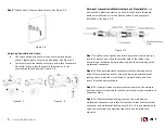
 If using the side exit, Follow Steps 1-2. Route the cable through 

the side notch of the base of the camera.

Figure 2-4

Figure 2-2

Figure 2-3

Summary of Contents for IPMX Series

Page 1: ...d Quali ed engineers needed All the examination and repair work should be done by the quali ed service engineers We are not liable for any problems caused by unauthorized modi cations or attempted rep...

Page 2: ...o highlight the object which is suitable for the surveillance function in the low illumination environments The waterproof design conforms to the IP67 level It has the sound waterproof function suitab...

Page 3: ...ure 2 1 Step 2 Install the expansion bolts if necessary Thread the base screws through the mounting holes in the base of the camera See Figure 2 2 Step 3 Pull the cables through if applicable and tigh...

Page 4: ...nstall the rubber ring into the network port keep the smaller hole of the rubber ring outward and install the xing rubber ring into the main body of the waterproof connector Step 2 Pull the network ca...

Page 5: ...igure 2 10 Step 3 If installing SD Card Adjust the Micro SD Card to a proper direction shown in Figure 2 10 Step 5 Close the access panel tighten down locking screw and reinstall camera Figure 3 1 3A...

Page 6: ...the click the Initialize icon on the bottom left side and follow the process on screen to initialize the device The Operate column will allow you to modify device view device information and link to...

Page 7: ...ng network camera address to check if connection is OK or not 4B LOGIN AND LOGOUT Open IE or Chrome and input the network camera address in the address bar See Figure 4 1 7 www icrealtime com Figure 4...

Page 8: ...n 8 www icrealtime com Figure 4 3 Web includes several modules monitor channel preview system con guration alarm and etc See Figure 4 3 Live Live video of camera Setup For con guration changes Alarm F...

Page 9: ...will need to specify the port number after the IP ex http 192 168 1 108 8080 Ensure the correct login credentials are being used The Smart ICRSS software will use the TCP port Make sure you input the...

Page 10: ...pollution any bodily injury or damage to any assets The consumer is not authorized to process such kind of substances or elements please return to the corresponding local authorities to process accord...

Reviews: