1. When connect VTO to electric lock, make electric lock + toward VTO NO-end
(02.3-pin 1) and electric
– toward VTO COM-end (02.3-pin 3).
2. When connect VTO to unl
ock button, make unlock button’s one end toward VTO (03.
3-pin 2) ALM 2-
end and unlock button’s other end toward VTO (03.3-pin 3) GND-end.
See Figure 4- 2.
Step 3 Install door sensor
Figure 4- 3
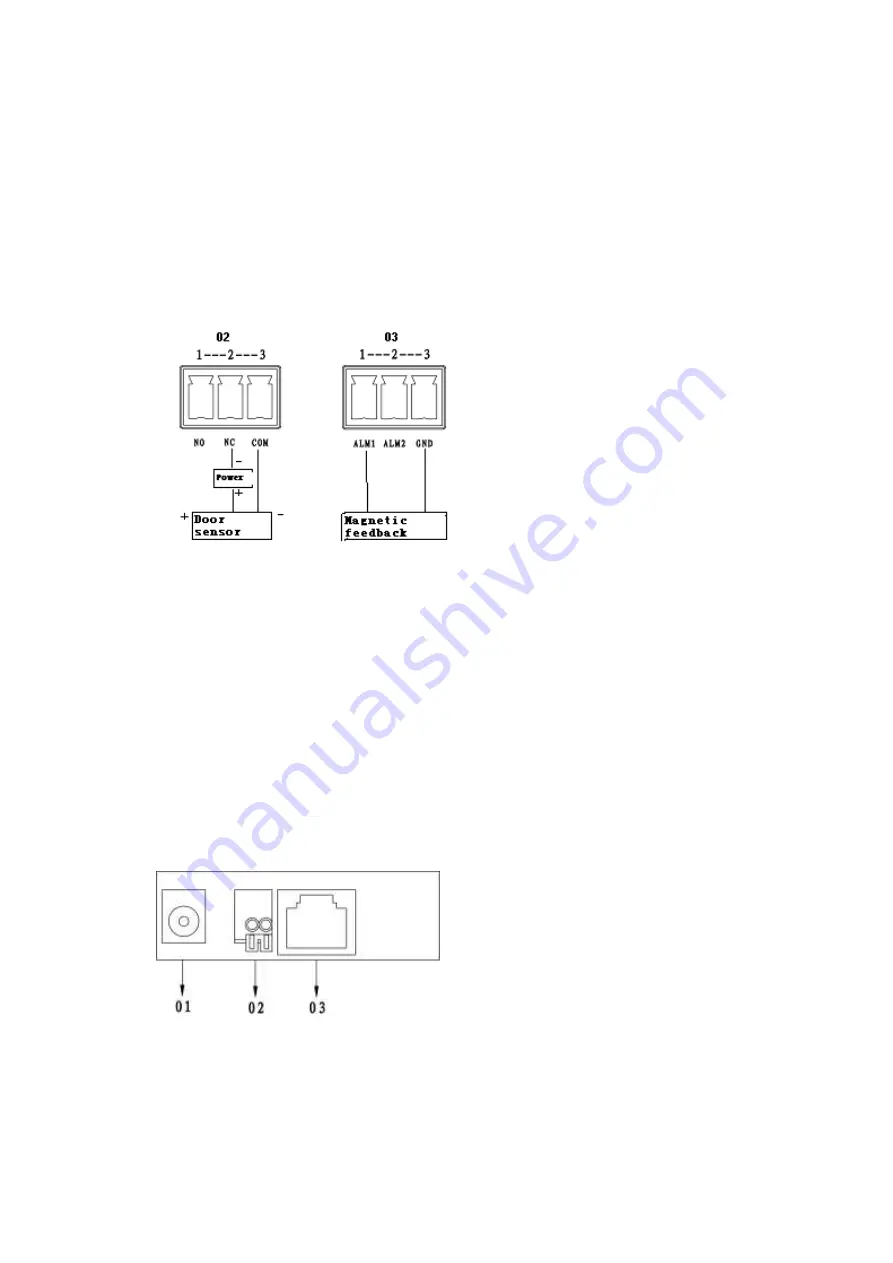
1. When connect VTO to door sensor, make door sensor + toward VTO (02.3-pin 2)
NC-end and door sensor
– toward VTO (02. 3-pin 3) COM-end.
2. When VTO is connected to door sensor for its magnetic feedback, make magnetic
feedback’s one end toward VTO (03. 3-pin 1) ALM1-end to unlock and make magnetic
feedback’s other end toward VTO (03. 3-pin 3) GND-end.
See Figure 4- 3.
Step 1 Definition of ports:
VTH can be connected to any port on VTO.
Figure 4- 4
01. Power port: to input DC 12V.
02. Lock port: to access control module
03. Network port: to switch (switch IN port)


