background image

 iCanView110/110W User’s Guide 


Rev.1.4 (Jan. 2005) 

30 of 56 


5.5. CCD Adjustment 

 
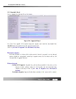
You can optimize the quality of input video by adjusting the parameter of CCD. To enter into this 
mode, click “

CCD Adjustment

” in administrative page. You will find a screen shown in Figure 5-6. 


Click “SAVE” to save the parameter after you finish the parameter setting.


Figure 5-6. CCD Adjustment 


y


CCD Type 

Either NTSC or PAL type CCD sensor is installed in iCanView110. Type of CCD is identified 
by the system and shown in this field. 


y


Lens Selection 

Any lens having CS mount type can be installed on iCanView110. Standard iCanView110 is 
delivered with C mount type fixed lens. In order for the convenience of replacement with CS 
type, a C-CS adaptor is packaged with iCanView110. 
Confirm whether your lens is Non DC IRIS or DC IRIS lens before your selection and then 
click “

SAVE

” to save your selection. 

Summary of Contents for iCanView 110

Page 1: ...iCanView110 110W User s Guide Rev1 4 Jan 2005...

Page 2: ...to correct the interference by one or more of the following measures z Reorient or relocate the receiving antenna z Increase the separation between the equipment and receiver z Connect the equipment...

Page 3: ...p transfer Caution Any changes or modifications in construction of this device which are not expressly approved by the party responsible for compliance could void the user s authority to operate the e...

Page 4: ...IP Installer 20 4 1 Main window of IP Installer 20 5 Configuring the A V Server in Administrative Mode 21 5 1 Log On 21 5 2 Basic Setup 23 5 3 Network Configuration 25 5 4 Wireless Configuration 28 5...

Page 5: ...is a model having Ethernet interface while iCanView110W is a model having embedded WiFi interface 1 2 Features of iCanView110 y 1 channel real time Video Audio streaming based on MPEG 4 video and ADPC...

Page 6: ...05 6 of 56 y Real time Internet broadcasting resort areas events etc y Remote monitoring hospitals kindergartens traffic public areas etc y Teleconference Bi directional audio conference y Remote Lear...

Page 7: ...e AC 250V 10A 16A LAN cable 2m LAN cable Crossover type For direct connection between the server and PC Antenna 3 dBi Omni antenna iCanView110W only CD ROM Software User s Guide Quick Reference Guide...

Page 8: ...anView110 is in normal operating condition Continuous green light indicates that iCanView110 is ready for transmitting data Flickering green light means that someone is connected to iCanView110 2 Red...

Page 9: ...audio source or microphone to iCanView110 If external audio is connected embedded microphone will be disabled y LINE OUT It is used for connecting external speakers with built in amplifier Audio from...

Page 10: ...ard Alarm In It is used for connecting external alarm sensors such as the infrared sensors heat sensor magnetic sensors etc Alarm Output It is used for connecting external alarm generators such as sir...

Page 11: ...iCanView110 110W User s Guide Rev 1 4 Jan 2005 11 of 56...

Page 12: ...vided in this section For more detailed information you are recommended to refer to pertinent documentations provided with the product or refer to iCanTek s home page http www icantek com 1 Connect iC...

Page 13: ...upload speed of your network Frame Rate It indicates the number of frames to be transmitted per second Basic Setup Video Rate It indicates the bandwidth allowed for video transmitted from iCanView110...

Page 14: ...amplifier 1 Alarm In Connecting Alarm Sensor IR sensor Motion Sensor Smoke Detector 2 Alarm Out Connecting Alarm alerting device Siren Flashing Light 2 RS485 PTZ device control Remote P T Z control ha...

Page 15: ...using the IP Installer 3 1 Connecting to LAN In case of connecting the iCanView110 to LAN it is generally connected as follows Figure 3 1 Figure 3 1 Connecting the iCanView110 to LAN 1 After applying...

Page 16: ...to xDSL Modem 1 Apply power and connect the PC and iCanView110 using crossover LAN cable provided with the system 2 Setup network parameters by running IP Installer Figure 3 2 Direct connection using...

Page 17: ...ally regular LAN cable is required But since some xDSL Modems has crossover connections please contact your xDSL provider for detailed information When fixed IP address is assigned to the xDSL follow...

Page 18: ...using crossover LAN 3 Remove the crossover cable and connect the iCanView110 to the network using regular LAN cable as shown in Figure 3 5 Check if you can receive video data when connecting to iCanV...

Page 19: ...Cable Modem follow the same way as assigning IP address for the case of LAN using IP installer To enable the notification of the changed IP address to the user over e mail when the IP address is chang...

Page 20: ...address and setup network parameters to digital video security network products such as Network Camera and A V Server IP Installer is provided in a CD supplied with iCanView110 or it can be downloaded...

Page 21: ...address window of the Internet Explorer http iCanView110 IP address admin htm Example http 172 16 64 133 admin htm If you changed the HTTP port from default value you can login by typing in http iCan...

Page 22: ...creen Factory default User Name and Password are set as root and dw2001 respectively Click on OK button to enter into the Basic Setup page of Admin Mode If you have changed the username and password o...

Page 23: ...iCanView110 It is same as the one set up by IP installer You can reassign the system name in admin mode y Audio Input Selection Select the type of input audio for each channel Line In is used for con...

Page 24: ...dth for transmitting audio data Audio data is not transmitted if you select NA y Check After you finish set up of video and audio for all the channels check this box to obtain the possible maximum num...

Page 25: ...arameters appropriately in accordance with your network environment Many of the parameters in this page is same as those used setup by IP Installer y IP Assign Type The network types supported by the...

Page 26: ...default 554 y IP Filtering You can restrict the access to the administrator page from IP addresses beyond certain IP address range Restrict Administrator Access Check this box to restrict administrati...

Page 27: ...is box to enable log on to the Management Server By log on to the management server your network camera can use domain name instead of number based IP address This feature is particularly useful when...

Page 28: ...N Select Enable to use wireless interface If Disable is selected Ethernet interface is used instead of wireless LAN interface SSID Enter the ID of the wireless LAN access point to be connected when wi...

Page 29: ...s Point In general the MAC address of the Access Point is shown Current Channel Indicates the channel number of present connection Signal Strength Indicates the strength of the received signal Link Qu...

Page 30: ...ing Figure 5 6 CCD Adjustment y CCD Type Either NTSC or PAL type CCD sensor is installed in iCanView110 Type of CCD is identified by the system and shown in this field y Lens Selection Any lens having...

Page 31: ...nsation Off Flickerless Enable In case of using NTSC type iCanViewV110 in 50Hz AC regions or using PAL type iCanView110 in 60Hz AC region video output tends to flicker when iCanView110 is used under f...

Page 32: ...e shutter speed since the opening of the IRIS is automatically adjusted But in case of NON DC IRIS lens the brightness of the video will change as you adjust the shutter speed When you are using your...

Page 33: ...assign different attributes for each user y User Administration Administrator Username Admin ID Default ID is root Password Admin password The default password is dw2001 Confirm Password Enter the pa...

Page 34: ...e specific user by clicking the DELETE button y Authentication for Viewing If you want to restrict viewing access to the iCanView110 check Yes box and click on Save Users need to input ID and password...

Page 35: ...Jan 2005 35 of 56 Time Settings You can set the time manually or you can synchronize the time to the PC Options Description Synchronize With Computer Time Synchronize the time with the PC time Set Ma...

Page 36: ...ndition y Video Capture Condition It sets the condition of video recording and transmission via FTP or E mail The iCanView110 supports 2 types of conditions 1 Sensor initiated when at least one of the...

Page 37: ...o Section 5 3 If the FTP server is not properly assigned in Network Configuration mode iCanView110 ignores the video transmission by FTP Captured video data for E mail consists of intra frames only in...

Page 38: ...f alarm y Alarm Device Test Test alarm devices Press On Off for testing y Alarm Device Active Condition Setup the condition of activating alarm Device Select sensor or motion detection as the conditio...

Page 39: ...vity Set the sensitivity in motion detection for each channel 1 is the least sensitive number and 66 is the most sensitive number Sensitivity values can be set to be different among channels but same...

Page 40: ...show the coordinate value automatically Next you press the END button and click the other diagonal corner Regions are shown in three different transparent colors red region 1 green region 2 blue regio...

Page 41: ...odel Selection Choose the PTZ model for each channel Different PTZ model can be applied for each channel Delete Button Press this button to delete the setup of PTZ y PTZ Device ID PTZ device can have...

Page 42: ...of the PTZ devices Left Right UP DOWN AUTO FOCUS ZIN ZOUT y PTZ Position Setup You can set up the PTZ limitation preset positions if the PTZ device supports it Panning Limitation set the left right li...

Page 43: ...e encryption check at the box at the left of the Enable data encryption then check at the proper check boxes at the left of Video and Audio After the selection click on SAVE button beneath the Video a...

Page 44: ...ncryption is enabled the PC client program will ask for particular key value out of the 20 available key values Uploading key value to the video server The key value stored on your PC can be uploaded...

Page 45: ...pgrade is a feature that enables network camera to upgrade to newly released system software by automatically connecting to upgrade server Click on check button to find the availability of upgrade fir...

Page 46: ...t Setting Re initialize iCanView110 to factory default state By checking on a Radio button Except Network Configuration you can preserve the paramteres for the network Checking on All will return all...

Page 47: ...Rev 1 4 Jan 2005 47 of 56 5 13 Status Report It shows you system records since the system started You can check the problems as well as the versions and event status of the whole system and each modu...

Page 48: ...ed sensors motion sensors heat smoke sensors magnetic sensor etc ALARM OUT t is used for connecting alerting device such as loud speaker flashing light etc Figure 6 1 ALARM IN ALARM OUT Connector 1 AL...

Page 49: ...ces or for remote on off devices such as light control Relay circuits are normal open and circuits are closed upon alarm output or remote on The relay is capable of switching AC DC 30V 1A electrical s...

Page 50: ...ly Open CollectorType Photo Coupler 3 2Connection of Relay Alarm Out Device Relay1 Power Supply 1 30 VDC AC 1A Relay1 Relay Switch Power Supply 1V 30VDC AC 1A Optional Relay Switch Alarm Out Device Po...

Page 51: ...e server is properly connected If you do not see a Reply message check if the network cable and power cable are properly connected Name of the channel on iCanView110 is displayed but there is no video...

Page 52: ...et it higher the video image can be corrupted with artifacts Ask your network manager or ISP for maximum uploading bandwidth of the network The image is dull and I see green pink dots This could be ca...

Page 53: ...address or host address in the address input field of the internet explorer Figure 6 4 Web Viewer of iCanView110 z Control Panel of Web Viewer Enable bidirectional audio When bidirectional audio is e...

Page 54: ...2 Half 1 2 Full Screen full On off the relay by pressing the button Shows the status of the sensor Blue color means that the sensor is in normal state while red color indicates alarm situation Number...

Page 55: ...tor is blinking You will find a screen as shown in Figure 5 12 Click UPGRADE button to start the upgrade 3 The server will notify the end of upgrade process on your screen 4 Click Confirm button on th...

Page 56: ...ake some time 6 Upgrade completion message will appear after the system upgrade has been completed 7 Reboot iCanView110 by performing System Reset 8 After rebooting log on to the server in administrat...

Reviews: