background image

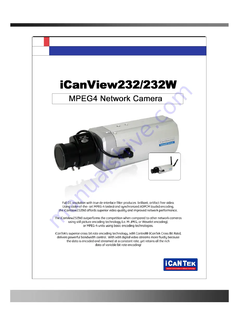
iCanView232

 User’s Guide 


Directions 


iCanView232 is designed for indoor use only. When using iCanView232 outdoors or in an 

environment that exceeds the limited range, you must separately use a water-resistant case.   


Be careful not to cause any physical damage by dropping or throwing the iCanView232. 

Especially keep the device out of reach from children.   


Do not disassemble iCanView232. You will be excluded from After Service when disassembled.   


Use only the power adapter provided with the iCanView232. 


If you would like to use the iCanView232 for security, monitoring, please check the legal 

regulations within the country.


Rev1.0(Feb. 2008) 

Summary of Contents for iCanView232

Page 1: ...areful not to cause any physical damage by dropping or throwing the iCanView232 Especially keep the device out of reach from children Do not disassemble iCanView232 You will be excluded from After Ser...

Page 2: ...communications However there is no guarantee that interference will not occur in a particular installation If this equipment does cause harmful interference to radio or television reception which can...

Page 3: ...pment Caution This appliance and its antenna must not be co located or operating in conjunction with any other antenna or transmitter A minimum separation distance of 20 cm must be maintained between...

Page 4: ...nstaller 19 4 1 Main window of IP Installer 19 5 Configuring iCanView232 in Administrative Mode 21 5 1 Log On 21 5 2 Basic Setup 23 5 3 Network Configuration 25 5 4 Wireless Configuration 28 5 5 CCD A...

Page 5: ...twork camera solution for system integration solutions To facilitate single cable installation iCanView232 are offered with standard PoE option IEEE 802 3af 1 2 Features of iCanView232 y 1 channel syn...

Page 6: ...e following conventions for the selection of the options and model names z Naming convention iCanView232 WPMT Basic model Options Basic model Basic Model Description Misc iCanView232 270K Sony CCD Fix...

Page 7: ...iCanView232 User s Guide N True Day Night IR cut filter Rev 1 0 Feb 2008 7 of 56...

Page 8: ...when standard PoE is not selected AC power cable AC 250V 10A 16A Standard Power cable supplied when standard PoE is not selected Antenna For Wifi option only CD ROM Software User s Guide Quick Refere...

Page 9: ...nView232 y Microphone Picks up sound from the environment for transmission over the network y Auto Iris Control Plug in the cable from standard DC Iris lens 2 3 2 Rear panel Lens Microphone WIFI Anten...

Page 10: ...standard 802 3af LINK LED Continuous yellow light means that network cable is plugged in It will flicker when there is traffic Status LED Green color indicates that the camera is in normal operation m...

Page 11: ...g video RS 485 Used for connecting Pan Tilt and Zoom devices having RS 485 interface standard SNS IN Connect external alarm sensors such as the infrared sensors heat sensor magnetic sensors etc NC NO...

Page 12: ...2 5 Quick Installation Guide Brief information for rapid installation is provided in this section For more detailed information you are recommended to refer to pertinent documentations provided with...

Page 13: ...tion When power is applied through standard PoE never apply power through AC adaptor iCantek assumes no responsibility for the damages caused by collision of the power through the standard PoE and AC...

Page 14: ...n Administrative Mode Note Set up values are preserved even the power is turned off Page Parameter Setup value Factory default value Basic Setup Video Size Set the resolution of the video transmitted...

Page 15: ...necting Alarm annunciating device Siren Flashing Light 1 RS485 PT device control Remote P T Z device connection having RS485 interface 1 100Base T 802 3af Network connection Connect iCanView232 to the...

Page 16: ...ou can receive video data when connecting to iCanView232 using the viewer program 3 Check if you can receive video data when connecting to iCanView232 using the viewer program 4 When one or more IP vi...

Page 17: ...d other network parameters to iCanView232 2 Install iCanView232 and connect it to xDSL or Cable modem as in Figure 3 2 Figure 3 2 Connecting the iCanView232 to ADSL Modem When fixed IP address is assi...

Page 18: ...refer to the Application note regarding Management Server in the CD When connecting iCanView232 to xDSL or Cable modem usually regular LAN cable is required But since some modems have crossover conne...

Page 19: ...P network parameters for connection to the network Internet Intranet IP Installer is a PC program for the initial network configuration to IP video products such as Network Camera or A V Server IP Ins...

Page 20: ...assigned and the initial connection is successfully made you can connect to the administration page for more sophisticated control of the network parameters and other operational parameters Refer to...

Page 21: ...s admin htm Example http 172 16 64 133 admin htm If you changed the HTTP port from default value you can login by typing in http iCanView232 IP address HTTP port admin htm Example http 172 16 64 133 8...

Page 22: ...nd Password are set as root and dw2001 respectively Click on OK button to enter into the Basic Setup page of Administrative Mode If you have changed the username and password of the Administrator you...

Page 23: ...the iCanView232 Figure 5 3 Basic Setup Field Button Sub Field Button Description Language Select a language of your choice System Name Logical name of the iCanView232 It is same as the one set up by I...

Page 24: ...r transmitting video data Audio rate Assign bandwidth for transmitting audio data Audio data is not transmitted if you select NA Check After you finish set up of video and audio for all the channels c...

Page 25: ...Configuration Setup the network parameters appropriately in accordance with your network environment Many of the parameters in this page are same as those set up by IP Installer Figure 5 4 Network Con...

Page 26: ...t this mode Refer to IP installer user s guide for Host name and domain for Cable Modem Clone MAC Refer to IP installer user s guide for Clone MAC Port Change Each port should have a number below 6553...

Page 27: ...FTP Server Setup Setup IP address Username Password and Directory of FTP server to send data in case of alarm Default FTP port number is 21 Management Server You can register the network camera to the...

Page 28: ...tton Description Wireless LAN Setup WLAN Mode Select ESS to use wireless interface If Disable is selected Ethernet interface is used instead of wireless LAN interface WLAN Radio Select the mode of Wir...

Page 29: ...AC address of the wireless LAN BSSID Indicates the ID of the connected access point In general the MAC address of the access point is shown Current Channel Indicates the channel number of present conn...

Page 30: ...er into this mode click CCD Adjustment in administrative page You will find a screen shown in Figure 5 6 Figure 5 6 CCD Adjustment Field Button Sub Field Button Description Lens Selection Standard iCa...

Page 31: ...e gain is automatically adjusted in accordance with the illumination condition Flickerless In case of using NTSC type iCanView232 in 50Hz AC regions or using PAL type iCanView232 in 60Hz AC region vid...

Page 32: ...iCanView232 User s Guide Original Values SAVE Click SAVE to save your selection Rev 1 0 Feb 2008 32 of 56...

Page 33: ...e 5 6 User Admin Time Setup You can change the ID and password of users and also assign different attributes for each user Figure 5 7 User Admin Time Setup Field Button Sub Field Button Description Re...

Page 34: ...ributes are Audio Bi directional Audio and Pan Tilt control z For example if you want a specified user to hear the audio from the iCanView232 check Audio in the check box User List You can list user i...

Page 35: ...ize the time with the internet time server at the right When the time server is out of the reach from iCanView232 you can assign time server by filling in Specific Time Server field Synchronize With t...

Page 36: ...ld Button Description Sensor Setup Sensor 1 Select sensor type There are two types of sensors which are Normal Open and Normal Close Name Input logical name for the sensor Video Capture Condition It s...

Page 37: ...By E Mail Check to send captured video by e mail E mail is sent to the Recv E mail address Refer to Section 5 3 Captured video data for E mail consists of intra frames only in consideration of the li...

Page 38: ...on On Off for testing Small box with white background indicates the status of the relay by On Off ON On the alarm output close the relay contact OFF Off the alarm output Open the relay contact Sound...

Page 39: ...arm generation upon sensor input Motion Check at the box at the left to allow alarm generation upon Motion detection Duration Set the duration of Alarm annunciation 10 sec 30 sec 1 min 2 min 5 min 10...

Page 40: ...3 regions can be defined Figure 5 11 Motion Region Setup Field Button Sub Field Button Description Channel Selection Not applicable Channel Sensitivity Set the sensitivity in motion detection for each...

Page 41: ...indicated with corresponding colors Legend of the color red region 1 green region 2 blue region3 START Enable selection of rectangular zone start END Enable selection of rectangular zone end SELECT C...

Page 42: ...etup Zoom is not applicable for iCanView232 Setup and test the PT Pan Tilt devices Figure 5 12 PTZ Setup Field Button Sub Field Button Description Channel Selection Not applicable PTZ Model Choose the...

Page 43: ...the panning limitation previously set The panning range will be the same as the PT device allows Panning Limitation SET Set the present position as left or right panning limitation Panning Limitation...

Page 44: ...ting the data from the network camera You can selectively activate encryption for the video and audio data For enabling the encryption check at the box at the left of the Enable data encryption then c...

Page 45: ...the network camera Click on SAVE button beneath GENERATE button to save the key value generated by the network camera DOWNLOAD Download Key value to your PC The key values can be downloaded and store...

Page 46: ...the system upgrade is performed Refer to 6 4 How to Upgrade Your iCanView232 System Field Button Sub Field Button Description Automatic Upgrade Automatic upgrade is a feature that enables network came...

Page 47: ...ew PT driver software via the network PT driver can be downloaded from iCanTek s home page Refer to 6 4 How To Upgrade Your iCanView232 System Factory Default Setting Re initialize the network camera...

Page 48: ...13 Status Report It shows you system records since the system started Figure 5 15 Status Report You can check the problems as well as the versions and event status of the whole system and each module...

Page 49: ...moke sensors magnetic sensor etc ALARM OUT is used for connecting alerting device such as loud speaker flashing light etc Figure 6 1 Terminal block for I O connection 1 ALARM IN Connect the two wires...

Page 50: ...ed for connecting alarm devices or for remote on off devices such as light control Relay circuits are normal open and circuits are closed upon alarm output or remote on The relay is capable of switchi...

Page 51: ...Open CollectorType Photo Coupler 3 2Connection of Relay Alarm Out Device Relay1 Power Supply 1 30 VDC AC 1A Relay1 Relay Switch Power Supply 1V 30VDC AC 1A Optional Relay Switch Alarm Out Device Power...

Page 52: ...2 If you see the Reply from message it means that the server is properly connected If you do not see a Reply message check if the network cable and power cable are properly connected 2 After Successfu...

Page 53: ...of the video Example is 704x480 video with low Max upload rate Users are recommended to adjust resolution and frame rates to lower values for lower bandwidth network 6 3 Web Viewer iCanView232 is desi...

Page 54: ...nView232 Rotate the screen by 180 degree Connect to iCanView232 Stop the connection Contrast Brightness and Volume adjustment Check the box to mute the audio Adjust the size of the screen Normal x1 Tw...

Page 55: ...ings are the procedure to apply for the manual upgrade 1 Save the upgrade system software to your PC Upgrade software can be downloaded from iCanTek s home page or provided in CD 2 Log on to administr...

Page 56: ...After rebooting log on to the server in administrative mode again and click the Status Report 9 Check the version number and release date of the iCanView232 You can download iCanView232 system softwa...

Reviews: