ICC
ETH-1000 Quick Installation Guide
Page 2
PN11145-1022
4.
Connect an Ethernet cable from an Ethernet switch to the ETH-1000 Ethernet port
5.
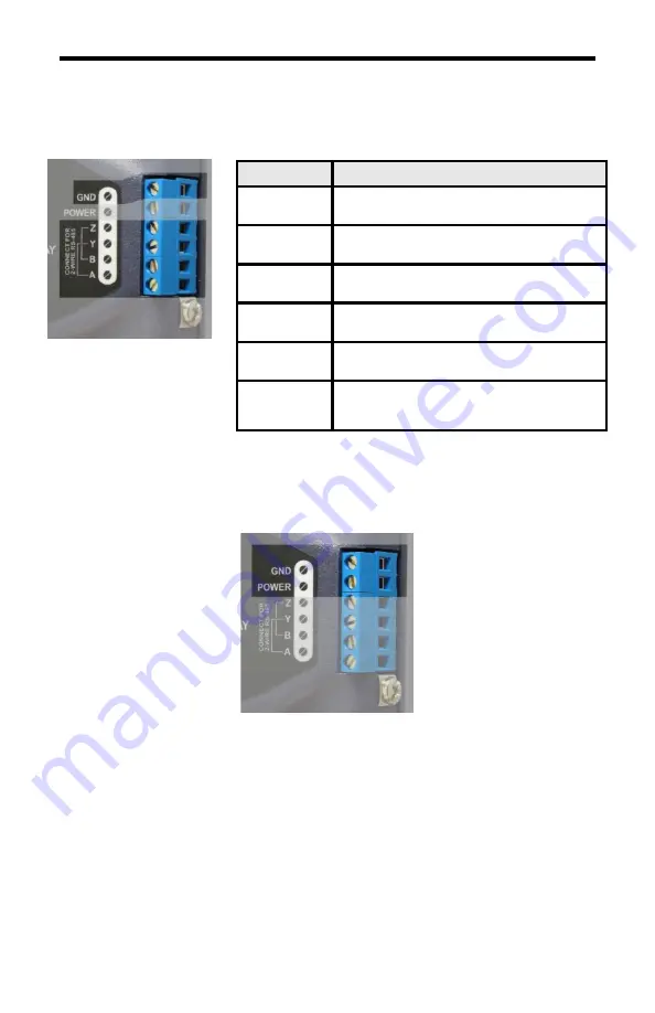
Connect the RS-485 wiring (for serial communication)
Note: 2-wire RS-485 requires a jumper between the A and Y
terminals and a jumper between the B and Z terminals
6.
Connect a power supply
•
7VDC to 24VDC
–
Connect only DC voltage to the POWER and GND terminals.
•
Power over Ethernet (PoE)
–
Ethernet port supports the IEEE 802.3af standard as a
mode A or mode B powered device (PD). Requires a PoE power sourcing
equipment such as a PoE endspan switch or midspan power injector.
•
USB
–
Temporary connection to configure, troubleshoot, and optionally power the
ETH-1000. USB cable may be connected while using any other power supply
option, but should be removed under normal operation.
7.
Installation is complete
Terminal
Network Connection
A
RS-485 Receive Positive (Non-Inverting)
RXD+ Data Signal
B
RS-485 Receive Negative (Inverting)
RXD- Data Signal
Y
RS-485 Transmit Positive (Non-Inverting)
TXD+ Data Signal
Z
RS-485 Transmit Negative (Inverting)
TXD- Data Signal
GND
RS-485 Common-Mode Reference
0V Ground
SHIELD /
Chassis GND
Cable Shielding Daisy-Chain Point
This screw has no internal connection
RS-485 terminals
7VDC to 24VDC power terminals


