238
ICC
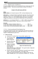
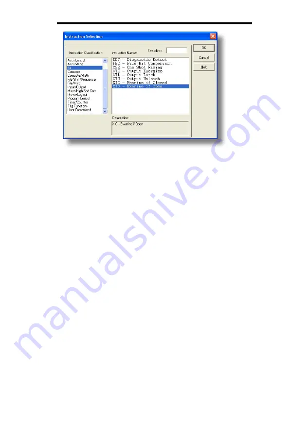
Figure 87: XIO Instruction Selection
5) Configure the MSG instruction.
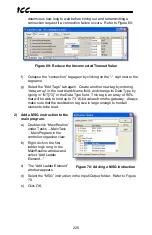
a) Set the “Read/Write” field to “Read”, “Target Device” field to “PLC5”,
“Local/Remote” field to “Local”, and “Control Block” to “N20:0”.
b) Upon hitting the <ENTER> key while in the “Control Block” entry box,
the MSG Properties dialog box should appear (or it can be opened by
clicking on the “Setup Screen” button at the bottom of the MSG
instruction). Refer to Figure 88.
c) In this example, we will be reading a total of 25 16-bit word values from
the database beginning at N30:50 (address 2050). To configure this,
under “This Controller” set the “Data Table Address” field to N18:1, set
the “Size in Elements field” to 25, and set the “Channel” field to 1
(Ethernet).
d) Under “Target Device”, set the “Data Table Address” field to N30:50
(starting target address=2050) and set the “MultiHop” field to Yes to
cause the “MultiHop” tab to appear.
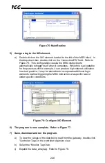
e) Under the “MultiHop” tab settings, set the “To Address” in the first row to
the gateway’s IP address, and the “To Address” in the second row to 0.
Refer to Figure 89.
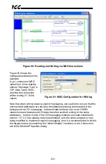
f)
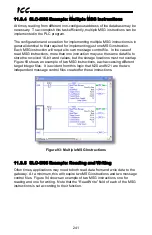
Close the dialog box. At this point, the program should appear as
shown in Figure 90.

