18
4.
RS485 Port Electrical Interfaces
In order to ensure appropriate network conditions (signal voltage levels, etc.)
when using the gateway’s RS485 ports, some knowledge of the network
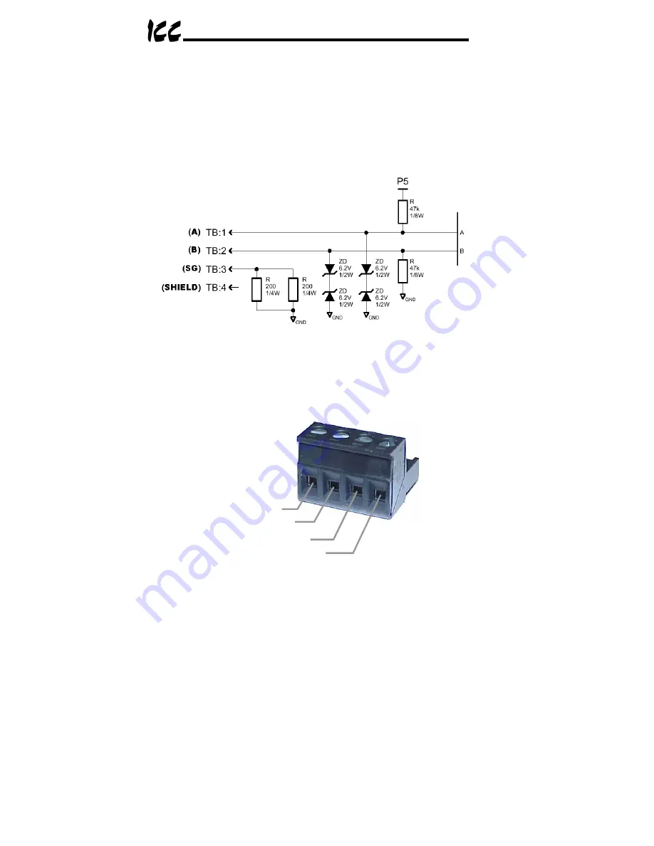
interface circuitry is required. Refer to Figure 4 for a simplified network
schematic of the RS485 interface circuitry. Note that the “Shield” terminal has
no internal connection: its purpose is simply to provide a cable shield chaining
location between devices. The shield is then typically connected to ground at
one location only.
Figure 4: RS485 Interface Circuitry Schematic
Figure 5 details the specific network connections to the RS485 terminal block.
This connection scheme applies equally to both RS485 ports.
A
B
Signal Ground
Shield
Figure 5: RS485 Terminal Block Connections
Summary of Contents for ETH-200
Page 101: ...100 18 Notes...
Page 102: ...101...


