Chapter 4-Installation for 1200XL
CHAPTER 4-INSTALLATION FOR 1200XL
Turn your computer on its back. Remove the six phillips head
screws which hold the case together and place them in your parts
dish. Turn the computer right side up and lift the top cover up and
towards the front. Look inside and find the two ribbon cables
which connect the keyboard and console LEDs to the main
computer board. Carefully unplug these cables noting the correct
polarity of their connectors. Remove the keyboard assembly and
set it aside for now.
Remove the six phillips head screws holding the computer board in
the bottom case. One of these screws is in the upper left hand
corner near the on/off switch. Another is in the upper right corner
and goes through the heat sink. The remaining four screws are
across the front and about four inches apart. (Three of these also
hold down the metal shield.)
Remove the computer board assembly from the case. Lift the front
of the computer board and the cartridge/joystick/switch assembly
up and pull the computer board out and towards you until all the
rear connectors are free. Remove this assembly, separate the
plastic piece from the PCB and set it aside.
Remove the metal shields and set them aside. There should be
several "push" rivets. Remove these then separate and remove the
metal covers. NOTE: Some metal covers are held together with
bent metal tabs instead of screws. These tabs should be
straightened with your needle nose pliers. Then the shields may be
separated.
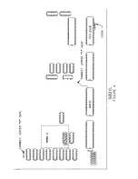
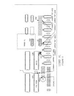
Locate Important Integrated Circuits (1200XL)
ANTIC-U20
Usually will be part number C012296. This is the 40
pin IC to the lower right of the PCB.
PIA-U23 Also labeled C014795 or 6520. This is located just
to the left of ANTIC in the 1200XL.
9


