Chapter 4-Installation for 1200XL
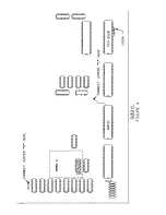
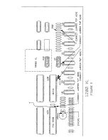
Bend out pin 3 of U7.
Remove U7 from its socket and bend out pin
3 as seen in figure 5. Plug this IC back into its socket. Pin 3 will
have jumper wire 'A' attached to it in the next step.
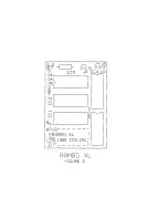
Connect all necessary jumpers.
See Table 2 and Figures 3 and 5.
Use 30 gauge hookup wire for the jumper wires. Solder them from
the pads on the RAMBO XL board to the locations on the computer
as indicated in Figure 5.
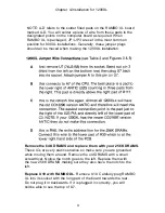
Bend out the 5 pins on the PIA and connect the ribbon cable.
Remove U23, the PIA IC. Bend pins 12-16 of U23 straight out (See
Figure 5). Slip the piece of shrink tubing over the ribbon cable and
then solder the ribbon cable from RAMBO XL onto the pins with
the black stripe towards the right (pin 16). Slip the shrink tubing
over the pins (to insulate them) and carefully heat the tubing just
enough to secure it from sliding back off the cable. Plug U23 back
into its socket with the ribbon cable over the top of VR1.
Place the PCB back into the case, plug the keyboard in, and test
operation.
Replace resistor R63 with a jumper wire.
1200XL is the only 8-bit
Atari computer with a current limit resistor (R63). This prevents
1200XL owners from using any peripherals (including the XM301
MODEM and P:R:Connection) which draw power from the
computer. We strongly recommend removing this resistor and
replacing it with a jumper wire to make your 1200XL more
compatible. R63 is located at the top of the PCB near the center. It
is just to the right of transistor Q3. Remove this resistor and
replace it with plain wire. Now you can use devices which draw
power from your 1200XL!
Reassemble your computer.
Test once again.
12


