background image

ELECTRICAL SEQUENCE

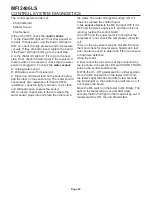
There are 7 indicator lights on the control board:

·

WTR-OK

(Water OK)

.

Green.

Normal =

Glowing. Glows when there is water in the
reservoir.

·

PWR-OK

(Power OK).

Green.

Normal =

Glowing. Glows when the control board has
power

and is functional.

·

Service.

Red.

Normally Off.

·

Freeze.

Red.

Normally glowing when making

ice.

·

Bin Full.

Red.

Normally Off when making ice.

·

LED1.

White.

Located next to the board’s

Compressor Relay (used to power the liquid line
valve). Normally Glowing when making ice.

·

LED3.

White.

Located next to the board’s Auger

Motor Relay. Normally Glowing when making
ice.

If the machine is switched off at the mode switch,
but is otherwise ready to go, switching the mode
switch to ON does the following:

·

The PWR-OK light glows.

·

If there is water in the reservoir the WTR-OK
light glows.

·

After 10 seconds the Freeze, LED1 and LED3
lights glow and the machine starts up.

Start Up:

·

The compressor relay and auger motor relay
become energized, connecting power to the
windings of the auger motor and liquid line valve
coil.

·

The liquid line valve opens, refrigerant flows to
the expansion valve and ice making begins.

·

As ice is made it passes between the ice level
sensors but because it is not a continuous
stream it only interrupts the sensor’s infrared
beam momentarily. The bin full light remains off
and the machine stays on until ice builds up in
the bin and blocks the path between the
sensors for 6 seconds or longer. When that
occurs the bin full light glows and the machine
shuts down.

Shut Down:

·

The compressor relay opens, LED1 goes out.

·

The liquid line valve closes.

·

The refrigerant flow stops.

·

The auger motor stays on for 1 more minute,
clearing out ice in the evaporator, and then

·

The auger motor relay opens, LED3 goes out
and the auger motor stops.

The liquid line valve will not re-open until 2 minutes
or more have passed after the last shut down.
If the path between the ice level sensors remains
clear for more than 10 seconds the ice machine
will restart.

Control Board Protection Devices

·

When the water level in the reservoir falls
below the water level sensor’s tip, the WTR-OK
light goes out and the machine shuts down.
When water refills the reservoir the WTR-OK
light glows and the machine starts up again.

·

If the auger drive motor current becomes
excessive the compressor and auger drive
motor will be switched Off and the Service light
will blink. The control board will restart the
auger drive motor in 4 minutes. If during the first
60 seconds after restart the auger motor current
stays within limits, the liquid line valve is
reopened and the machine returns to normal
operation. If the auger motor’s current is
excessive within 60 seconds after the restart,
the process will be repeated once more. If
during that try the current is still excessive the
machine shuts down and must be manually
reset. The service light will then be glowing
continuously.

To Reset: Disconnect and reconnect electrical
power to the unit.

The

mode (on - off)

switch is the manual control

for the complete machine, but it is not a service
disconnect.

MFI2406LS

Page 11

Summary of Contents for MFI2406LS Series

Page 1: ...Ice O Matic 11100 East 45th Ave Denver Colorado 80239 Part Number 9081358 02 17 3168 02 Date 10 08 SERVICE AND INSTALLATION MANUAL MFI 2406LS Series...

Page 2: ...SERVICE PARTS MANUAL 22 INCH WIDE ICE SERIES CUBERS MODEL ICE0320 ICE0520 Includes 50Hz Units ICE O Matic 11100 East 45th Ave Denver Colorado 80239 Part Number 9081297 01 PD04 02 Rev1 05...

Page 3: ...ART UP Page 7 COMPONENT IDENTIFICATION Page 8 COMPONENT DESCRIPTION Evaporator Page 9 CONTROL BOX Components Page 10 ELECTRICAL SEQUENCE Page 11 OPERATION Page 12 OPERATION Refrigeration Page 13 CLEAN...

Page 4: ...ance They meet or exceed the standards of U L N S F and C U L Ice O Matic assumes no liability or responsibility of any kind for products manufactured by Ice O Matic that have been altered in any way...

Page 5: ...ecommended for lifting the machine high enough to install on top of the bin Level the assembly by turning the leg levelers in or out Locate the Nameplate The nameplate is located on the back panel of...

Page 6: ...ring diagram The ice machine should be connected to it s own electrical circuit and be individually fused Voltage when the unit is under full load must remain within the limitations listed on page 2 L...

Page 7: ...e between the ice maker and the water supply Drain System All drains are of the gravity type and must have a minimum of 1 4 fall per foot of horizontal run The drains must be installed to conform to l...

Page 8: ...en removed from inside the cabinet 6 Have the electrical connections been made 7 Have the drains been installed and checked for leaks 8 Has the refrigeration supply been installed and checked for leak...

Page 9: ...egins to make ice Water flows from the water reservoir and the float drops letting in more water 7 Switch on the other master mode switch observe that The liquid line valve opens The gearmotor runs Wi...

Page 10: ...easure the temperature of the evaporator outlet at the TXV bulb and check the low side pressure at the EPR valve Convert the pressure to temperature using a temperature pressure chart and subtract the...

Page 11: ...ing action being where the two seal faces meet Ice Sweep A plastic cap with fingers It revolves with the auger to sweep the ice into the ice chute Divider Where the ice is compressed and much of the e...

Page 12: ...elays are for the gear motor with a built in time delay to clear the evaporator of ice when the unit turns off and for the liquid line valve See photo below On Off Mode Switch Manual control for that...

Page 13: ...occurs the bin full light glows and the machine shuts down Shut Down The compressor relay opens LED1 goes out The liquid line valve closes The refrigerant flow stops The auger motor stays on for 1 mo...

Page 14: ...voir which it enters through the float valve The water then goes out the bottom of the reservoir tank to the bottom of the evaporator Reservoir overflow or evaporator condensation is routed to the dra...

Page 15: ...lve The thermostatic expansion valve meters the liquid refrigerant into the evaporator where it boils off evaporates and absorbs heat It then moves through the ball valve and into the evaporator press...

Page 16: ...solution has been added to the reservoir and the reservoir is nearly empty switch the master switch to OFF 11 After draining the reservoir as in step 6 wash and rinse the water reservoir 12 Go thru s...

Page 17: ...ce chute and wipe the inside clean as illustrated 2 The ice machine senses water level by a probe located in the water reservoir At least twice a year the probe should be removed from the reservoir an...

Page 18: ...ease is needed the bearing and breaker should be removed to check the action of the bearing It should rotate smoothly To remove the breaker take out all four allen head cap screws and pull the breaker...

Page 19: ...Switch off electrical power and shut off the water supply For more information on removal of these parts see REMOVAL AND REPLACEMENT 1 To remove the auger remove front and top panel See Removal And R...

Page 20: ...uding bearings gear motor condition and scale on auger evaporator May also be due to liquid line valve leak thru during the off cycle Check valve Auger not turning Due to motor failure auger relay fai...

Page 21: ...the seal leaks shut off the water remove the auger replace the water seal Check gear motor for water infiltration Uses too much water Reservoir float valve leaks thru Replace float valve or seat Exces...

Page 22: ...e where the water sensor plugs into and place the other end in the water The water OK light should go ON If it does not replace the control board 3 Ice sensor check Is the Bin Full light Off If it is...

Page 23: ...acket and remove reservoir from ice maker 8 Reverse to reassemble BIN CONTROLS Ice Level Sensors 1 Disconnect electrical power 2 Remove front panel 3 Remove control box cover 4 Locate ice chute at the...

Page 24: ...damage a The bearing is pressed into the breaker to remove the bearing and replace it an arbor press is needed b Replace lower seals before installing new bearing in breaker Note seals must be pressed...

Page 25: ...rews holding breaker to evaporator d Lift up and remove breaker from evaporator e If the auger is stuck use a slide hammer type puller to pull on the auger at the threaded hole The size of that hole i...

Page 26: ...wn against it 3 The part of the water seal that rotates with the auger must also be replaced Remove the old part from the auger and clean the mounting area 4 Place a small bead of food grade silastic...

Page 27: ...Water Seal sweat in the new evaporator at the old connections 6 Install an new drier in the liquid line 7 Evacuate the system until dehydrated then weigh in the nameplate charge Check for leaks 8 Ins...

Page 28: ...quickly check the gears and bearings They are likely to be fine if the oil is If there is evidence of water in the oil rusty bearings and gears the oil having a creamy white appearance oil level too h...

Page 29: ...MFI Series Wiring Diagram 2406LS Page 27...

Page 30: ..._____________________________________________________________________________ __________________________________________________________________________________________ _______________________________...

Reviews: