background image


7


REMOTE REFRIGERATION SYSTEM  


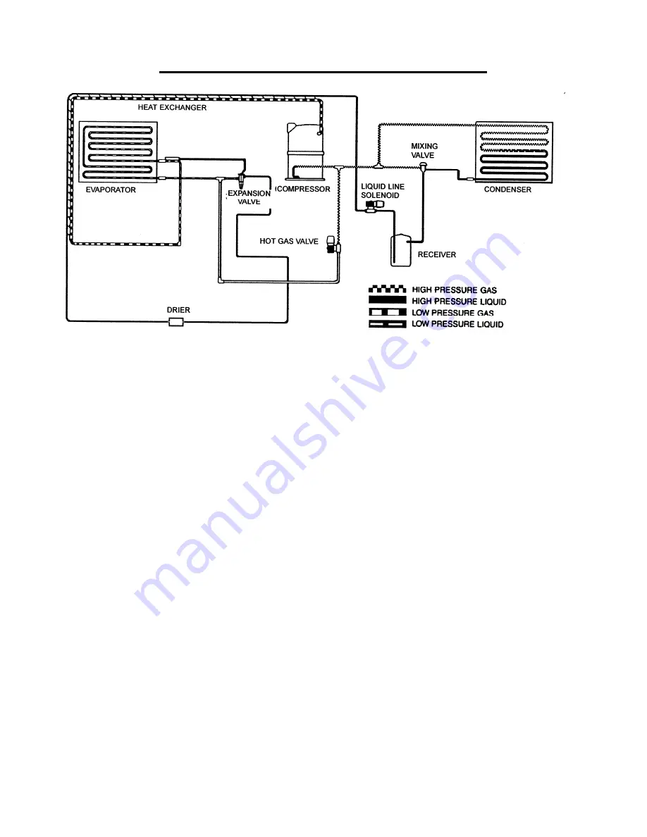
The Remote Refrigeration System is shown in the above diagram.  During the freezing cycle, high 
temperature and high pressure liquid refrigerant is directed from the condenser through a mixing valve, 
receiver, liquid line solenoid heat exchanger and a filter drier.  The expansion valve meters refrigerant to the 
coils on the back of the evaporator.   

In low ambient conditions (below 70

F air temperature at the condenser) the mixing valve opens to mix 

discharge gas with liquid returning from the condenser, in the receiver, to maintain discharge and liquid line 
pressures. 

The low temperature and pressure refrigerant leaving the evaporator is directed through the suction line 
heat exchanger and is returned to the compressor.  There it is compressed to a high temperature and high 
pressure gas.   It is then directed to a condenser to be converted again to a high temperature and high 
pressure liquid. 

During the harvest cycle, the hot gas solenoid valve (normally closed during the freeze cycle), opens and 
directs the high temperature gas leaving the compressor into the evaporator.  Once the evaporator has 
reached approximately 40

F, the harvest motor overcomes the capillary attraction of the ice and the 

evaporator releases the ice.  At the end of the harvest cycle, the hot gas solenoid valve closes and another 
freeze cycle begins. 

During the off cycle, the liquid line solenoid valve closes. 


Summary of Contents for RGA0501-HM

Page 1: ...Ice o Matic 11100 East 45th Ave Denver Colorado 80239 Part Number 9081487 01 Rev K INSTALLATION MANUAL REMOTE CONDENSERS RCA1001 RCA1061 RCA2061 RCA3061 RCA3561 RGA0501 HM RGA1061 HM...

Page 2: ...Service Parts Manuals are available separately Ice O Matic icemakers and dispensers are not approved for outdoor installation WARNING Always disconnect electrical power whenever maintenance or repair...

Page 3: ...ection Visible Loss or Damage Any external evidence of loss or damage must be fully described and noted on your freight bill or express receipt and signed by the carrier s agent The claim should be fi...

Page 4: ...enser and Ice Machine Pairing Page2 Installation Page 5 Remote Refrigeration System Page 7 Component Description Page 8 Electrical Connections Page 9 Condenser Leg Installation Page10 Refrigeration Tu...

Page 5: ...30 85 37 01 GRILL10 RGA1061 HM 30 85 30 85 37 01 GRILL10 The RGA models DO NOT have a Mixing Valve in the condenser The RCA and RGA models DO NOT include side grills they can be ordered as a Field Ins...

Page 6: ...ine Pairing Remote Condenser Ice Machine Model RCA1001 CIM0530R RCA1061 CIM0535R CIM0636R RGA0501 HM GEM0650R MFI0800R RGA1061 HM GEM0956R GEM1306R MFI1256R MFI1506R The RGA models DO NOT have a Mixin...

Page 7: ...Ice Machine Pairing Remote Condenser Ice Machine Model RCA2061 CIM0825R CIM0826R CIM0835R CIM0836R CIM0837R CIM1125R CIM1126R CIM1135R CIM1136R CIM1137R GEM2006R MFI2306R CIM1446R CIM1447R RCA3561 CI...

Page 8: ...4 Condenser and Ice Machine Pairing Remote Condenser Ice Machine Model RCA3061 CIM1845R CIM1545R...

Page 9: ...coil should not be exposed to temperatures below 20 F 29 C or above 120 F 49 C The remote condenser functions as a normal refrigeration system until the temperature at the condenser coil drops below 7...

Page 10: ...enser Maximum Rise is 35 feet Maximum Drop is 10 feet Maximum equivalent run is 100 feet Formula for calculating maximum equivalent run is as follows Rise x 1 7 Drop x 6 6 horizontal run equivalent ru...

Page 11: ...mperature and pressure refrigerant leaving the evaporator is directed through the suction line heat exchanger and is returned to the compressor There it is compressed to a high temperature and high pr...

Page 12: ...The quantity of liquid refrigerant in the receiver will vary with the temperature at the condenser coil Liquid Line Solenoid and Pump Down Low Pressure Control ICE Series ice machines When the bin is...

Page 13: ...e sure the supply voltage is the same as the rated voltage shown on the nameplate 5 Reference wiring diagram below for proper connections INSTALLATION NOTICE THE RCA RGA SERIES REMOTE CONDENSERS MAY O...

Page 14: ...nstalled on the base studs DO NOT remove the nuts Slide the legs in position and retighten the nuts Roof Attachment 1 Install and attach the remote condenser to the roof of the building using the meth...

Page 15: ...own with a vertical air flow 2 All excess tubing 1 should be routed inside the building and coiled in a vertical spiral as shown 3 to prevent oil trapping in the lines Any tubing run outside should be...

Page 16: ...the roofing contractor cut a minimum hole for the refrigerant lines of 1 750 inch Check local codes a separate hole may be required for the electrical power to the condenser CAUTION DO NOT KINK OR CRI...

Page 17: ...ertain that the threads are properly engaged 4b Using two wrenches one to rotate the swivel nut and one to hold the tubing tighten each coupling It is CRITICAL that ONLY the NUT on the pre charged tub...

Page 18: ...14...

Reviews: