SOLAR FRAME MOUNTING
Assemble frame(s), and if a different pitch than roof plane, upstand(s).
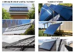
a) Assembly for same plane as roof (ie. collector mounted flat on roof).
1. Locate collector with suitable northerly orientation approximately 300mm below
ridge line to allow roof penetrations to be behind the solar collector’s manifold
giving enough clearance for pipes to clear the ridge support. Ensure that pen-
etrations are clear of other roof structural members, for ease of running pipes.
2. Use HDPE mounting blocks to ensure no part of the solar frame can come in
contact with the roof material. This will ensure no corrosion can occur due to
the effects of dissimilar metals. Drill clearance hole in centre of block.
3. Ensure manifold & foot-rail clips are bolted to ‘U’ channels before fixing onto
roof. The tongues of the clips to face the manifold/foot-rail lip with locking ‘U’
piece mounted inside of ‘U’ channel for ease of tightening at end of assembly
(see image).
4. Ensure 3 fixings can be achieved into roof purlin per ‘U’ channel.
NOTE: The foot-rail end of the ‘U’ channel is determined by the end that has
holes in the side that are used for a pivot point for connecting feet for when
an adjustable upstand is required for flat roofs.
5. Space rails at no more than 2.1mts apart (overall) for STD30 and 1.4mts
apart (overall) for STD20. Note that the fixings to manifold and foot-rail to ‘U’
channel are horizontally adjustable. Outer ‘U’ channels are to be installed
first and should be located no more than 200mm from edge of solar panel.
Fix only to the top of the roofing material profile (see cross section of roof fix-
ing) and select a profile that does not have existing roof screws, so as not to
interfere with existing roofing system manufacturer’s roof fixing requirements.
6. Drill a clearance hole for the roof mounting screw only slightly larger than the
roof screw and small enough that the roofing washer can provide a nice seal
against roofing material when tightened. (ie. place roofing washer between
roofing material and HDPE block) see roof fixing details.
7. When marking roof fixing points on ‘U’ channel, select the most suitable
purlins for fastening and mark on the rail the fixing positions. If some existing
fixing holes don’t quite suite, then drill clearance holes in the desired location.
8. For STD30 collectors that have 3 x ‘U’ channels. Once the two outer rails
are fixed, use the foot-rail as a straight edge and rest on the top of these rails
and fix the centre ‘U’ channel in the approximate centre bringing it to line up
with the straight edge.
9. ensure roof mounting screws are firmly tightened as to provide secure and
weather proof seal onto roofing material.
b) Assembly for different pitch as roof (ie. collector on adjustable upstand).
1. Bolt adjustable upstand together using the frame assembly image as a guide,
the pieces are numbered and marked on the image for easy assembly.
2. Locate collector with suitable northerly orientation approximately allowing for
roof penetrations to be behind the solar collector’s manifold giving enough
clearance for pipes to clear the roofing support members. Ensure that pene-
trations are clear of other roof structural members, for ease of running pipes.
3. Use butynol strip or suitable material to separate the powdercoated alumini-
um feet from roofing material to avoid effects of dissimilar metal corrosion.
4. Ensure manifold & foot-rail clips are bolted to ‘U’ channels before fixing onto
roof. The tongues of the clips to face the manifold/foot-rail lip with locking ‘U’
piece mounted inside of ‘U’ channel for ease of tightening at end of assembly
(see image).
Please note: Insulation is not to run through the roof flashing


