PLUMBING RETROFITTING
when fitting to existing non-solar cylinders
Please also observe the instructions above for plumbing with these added notes
A. Turn off power from Main Circuit Breaker (MCB), turn off isolation switch.
B. Drain Cylinder and remove cold feed.
C. Drill though baffle with clearance hole to take riser pipe. NOTE: Baffles
behind cold feed side entry ports pull the cold water from lower down in the
cylinder, therefore allowing a higher return position when 4-Way riser pipe is
inserted horizontally through a this clearance hole.
D. Connect riser to 4-Way valve and insert valve into cylinder.
E. Reconnect cold feed to one side of 4 way valve.
F. Connect Solar Out to other side of 4-Way valve ball valve.
G. Connect Solar return to riser pipe end of 4-Way valve.
H. Connect a tempering valve (anti-scalding device) if non present. Use high
temperature rated valves only - suitable for wetback and evacuated tube
solar systems that can produce extra high temperatures.
Controller is pre-programmed and pre-wired for ease of installation
• Mount controller terminal box, display and relay
• Controller terminal box is best located in the close proximity to the cylinder,
as the most of the probes are fitted to the cylinder and they have a 3mt cable
length. The terminal box is best positioned at chest to eye height (1.4mt-
1.7mt) from floor level for ease of future maintenance/access.
• The controller terminal box requires a standard 3 pin power socket (10amp)
to plug into, and is best located within 1 metre below the proposed location of
terminal box. The power cable for the terminal box is 1 metre long.
• The display for the controller is best positioned at the end user’s eye level
in a well lit area, usually hallway outside cylinder cupboard where there is
sufficient light. Check that there is a light that will cast direct light onto the
display so the buttons can be clearly read at night if required. Display cable is
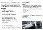
5metres. Remove plastic protective coating over glass display screen once
building work/painters have finished.
• Solar cylinders should have probe sockets, though some brands of solar
cylinders do not have sensor sockets that line up for full functionality of this
system and therefore will require some retrofitting of probes (see retrofitting
below). All Ice Solar cylinders have probes in the correct position.
• Insert probes into cylinder as per schematic. Ie. T2 to reads bottom of tank,
T3 mid and T4 top. (probe locations may differ for advanced installs).
• Probes need to be well secured so that they are taking accurate tempera-
ture readings. Best Method for standard probe sockets is as follows: drill a
clearance hole through the plastic cap of cylinder to take the probe cable.
Feed the probe through the cap, then insert the probe all the way into the
horizontal thermocouple sleeve inside the cylinder. Apply neutral cure sili-
cone just inside the outer casing of the cylinder under the cap, then insert the
cap. Use tape to hold cable in place for minimum 24 hours to allow silicone
to cure.
• Once probes are secure clip cables using cable ties back to terminal box and
trim excess cable to make a tidy job. IMPORTANT: secure probe wires away
from hi voltage electrical cables such as the element cable, pump and con-
troller electrical cable. Hi voltage can interfere with sensitive probe wires.
• Ensure all electrical and sensor wires are protected from moisture.
• Pump simply plug into 3 pin female socket that is attached to controller.
NOTE: It is not recommended to hard wire the pump for ease of future main-
tenance. Remove excess cable for a tidy job and reconnect to terminal box.
• When plumbing complete, then plug in controller and turn on power.
• Set time clock by pressing Clock “+” “-” to adjust hours, then press clock “+”
“-” to adjust minutes, then press clock again to lock in.
• All set points are already preprogrammed as per the owner’s manual. For
advanced installations then please seek advice for specific settings changes.
WIRING
when fitting to existing non-solar cylinders
Please also observe the instructions above for wiring with these added notes
Probes need to read accurately so that the controller operates correctly within it’s
set parameters. For the best reading on a non solar cylinder, the probes need
to be resting vertically against the inner barrel of cylinder. Ie. so that the full
length of probe has metal to metal contact. When the probes are tucked under
the insulation, the insulation maintains pressure to keep the probe in place and
against the barrel. Barrels are rounded, so the reading will no be so accurate if
the probe is installed horizontally.
• T2 is to be located approximately at approximately at the level of cold ‘solar
out’ at the bottom of the cylinder.
• T3 is to be located, above the point of hot water return from solar panel and
also above the element. For a single element cylinder, this is best achieved
by opening element cover and scraping away the insulation for a path for the
probe with a long flat screw driver against the inner barrel as high as possible
above the element.
• T4 is to be located in the upper portion of cylinder approximately 1 shower
worth (40-50Litres) from the top. Take into consideration the insulation at
top of cylinder, this would generally be 350-450mm from top of tank. Using a
gauge to ensure the inner barrel can not be damaged, drill through the outer
casing with a 9mm drill. Using some 2mm wire (coat hanger wire) create a
path through insulation so that the probe will end up flat against the barrel.
Ie. the probe will end up above or below the hole you drill and end up at ap-
proximately at the level of approximately 40 Litres.
WIRING RETROFITTING


