background image

ICE iS1100L

         53

          OPERATOR

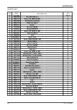
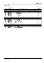
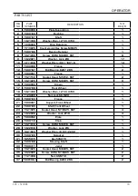
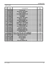
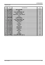
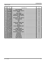
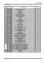
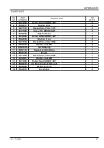
PARTS LIST

DIA        

NO

PART          

NUMBER

DESCRIPTION

NO          

REQ'D

1

1123810

Nut,Lock,SS,M8

2

2

1411816

Washer,Plain, 8X 16X1.6

4

3

7000146

Spacer

2

4

7000139

Hopper Wheel

2

5

1521640

Socket Head, M6X40, SST

4

6

1421612

Washer,Plain, 6X 12X1.6

4

7

7000145

Handle

1

8

1421618

Washer,Plain, 6X 18X1.6

4

9

1123608

Nut,Lock,SS,M6

4

10

7000181

Latch

1

11

7000140

Cap

2

12

1521612

Socket Head, M6X12, SST

2

13

1422616

Washer, Lock, Ø6

2

14

7000138

Hopper

1

15

1022890

Screw, RHM, M8X90, SST

2

16

7000141

Plate

1

17

7000232

Handle Assembly

2

18

1021516

Screw, RHM, M5X16, SST

8

19

1123507

Nut,Lock,SS,M5

8

20

1421510

Washer,Plain, 5.3X 10X1

8

21

7000238

Left Bocket

1

22

7000236

Right Bocket

1

23

7000237

Kit Left Bocket

1

24

7000235

Kit Right Bocket

1

25

7000137

Hopper Assembly

1

Summary of Contents for iS1100L

Page 1: ...Operator Parts Manual Ride on Auto Sweeper www icecompanies com 7000704U REV 01 08 2018 iS1100L INTELLIGENT CLEANING EQUIPMENT www icerental com ...

Page 2: ...tomer ID number billing and shipping address phone number and purchase order number Model No Serial No Machine Options Sales Rep Sales Rep phone no Customer ID Number Installation Date READ OPERATOR MANUAL MANUAL CAREFULLY ICE Company Limited XiangShi Road LiaoBu DongGuan GuangDong China Tel 0769 8186 9000 Fax 0769 8186 300 PROTECT THE ENVIRONMENT Please dispose of packaging materials old machine ...

Page 3: ... 17 MAIN BRUSH REPLACEMENT 18 SIDE BRUSH HEIGHT CHECK AND ADJUSTMENT 19 SIDE BRUSH REPLACEMENT 19 DUST FILTER CLEANING AND INTEGRITY CHECK 20 SKIRT HEIGHT AND OPERATION CHECK 21 BATTERY CHARGING 22 FUSE CHECK REPLACEMENT 23 ALARMS TROUBLESHOOTING 24 SCRAPPING 24 PARTS LIST 25 CHASS ASSEMBLY 25 26 BODY ASSEMBLY 27 29 MAIN BRUSH ASSEMBLY 30 32 RIGHT SIDE BROOM ASSEMBLY 33 34 LEFT SIDE BRUSH ASSEMBLY...

Page 4: ...ul functions Pay careful attention to the paragraphs marked by this symbol NOTE It indicates a remark related to important or useful functions GENERAL INSTRUCTIONS Specic warnings and cautions to inform about potential damages to people and machine are shown below DANGER Before performing any maintenance repair cleaning or replacement procedure disconnect the battery connector remove the ignition ...

Page 5: ... and or covers Do not use the machine in excessively dusty areas Do not wash the machine with direct or pressurised water jets or with corrosive substances paragraph While using this machine take care not to cause damage to other people and children especially The machine storage temperature must be 32 F to 104 F 0 C to 40 C The machine working temperature must be 32 F to 104 F 0 C to 40 C The hum...

Page 6: ...e emergency push button turn it in the direction shown by the arrow 16 Left cover to be opened for performing maintenance procedures only 17 Cover nuts 18 Flashing light always on when the ignition key is turned to I 19 Driver s seat with safety microswitch 20 Seat longitudinal position adjusting lever 21 Led light 22 Working light optional 23 Right side brush height adjusting knob 24 Left side br...

Page 7: ...n it is full 29 Hopper fastening hook 30 Hopper handle 31 Exhaust hole 32 Hopper wheel 33 Right cover for main broom removal 34 Door knobs 35 Tool Holder 37 Cover knobs 38 Internal containers with handle for dumping 39 Serial decal 28 29 30 31 32 34 33 35 36 37 4 39 25 38 38 ...

Page 8: ...er 48 Machine connector 49 Main broom height adjusting knob 50 Vacuum Fan cover 51 Vacuum fan 40 Body rope 41 Li_ion batteries or optional gel batteries GEL 42 Battery connection diagram 43 Battery caps for WET batteries only 44 Battery connector 45 Battery container 40 44 41 43 42 41 50 51 49 47 45 46 48 41 ...

Page 9: ...tery charger 58 Charged battery warning light 59 Electrical component box 59a Lamellar fuse box cover 52 Drive system electronic board 53 Drive system malfunction led If the led is on the drive system is operating if the led ashes the drive system is malfunctioning 54 Pillar 55 Main fuse 52 53 57 58 54 55 56 59 59a ...

Page 10: ...he following accessories options according to the machine specic use Main and side brooms with harder or softer bristles Working light Skirts of various materials Protective roof For further information concerning the optional accessories contact an authorised Retailer 62 61 69 70 71 72 60 73 At power on the display shows battery voltage hourmeter and software release for about 1 second Then syste...

Page 11: ...ity 21 2 gal 80 liters Main brush motor 0 67 HP 500 W Side brush motors 0 1 HP 80 W Drive system motor 0 8 HP 600 W 110 rpm Vacuum system motor 0 41 HP 310 W Filter shaker motor 0 13 HP 100 W 6 500 rpm Sound pressure level at workstation A Lpa 63 8 dB A Vibration level at the operator s arms 8 2ft s2 2 5m s2 Vibration level at the operator s body 1 9ft s2 0 6m s2 Under normal working conditions on...

Page 12: ...G RD 7 18AWG RD 7 18AWG RD 7 18AWG RD 7 18AWG BK 0 18AWG RD 29 18AWG RD 28 18AWG BU 0 18AWG BN 29 18AWG BK 0 18AWG RD 29 18AWG BK 0 18AWG RD 29 18AWG RD 28 16AWG BK 0 16AWG BK 0 2 2 18AWG RD 1 18AWG 2 RD 18AWG 4 BN 18AWG 4 BN 18AWG 29 RD 14AWG 9 GY 14AWG 8 WH YE 27 GN 6 BK 0 10AWG 13 BU 10AWG 12 BN 8AWG BK 8AWG RD 10AWG 15 BK 10AWG 14 RD BU BN YE GN 4 18AWG WH 18 18AWG BK 31 18AWG BN 32 3 6AWG RD ...

Page 13: ...ard fuse 5A Fuse4 i SYNERGY SW i SYNERGY starting up switch K2 Working light switch L1 Working light L2 Led light L3 Flashing light left L4 Flashing light right M1 Drive system motor M2 Main brush motor M3 Vacuum fan M4 Right side brush motor M5 Left side brush motor M6 Filter shaker motor Pedal Drive speed potentiometer pedal Out1 Electrobrake output SWS Emergency push button SW1 Driver s seat sa...

Page 14: ...s are connected to the machine with the connector 44 Connect machine i synergyTM COM port to the batteries 2 Close the body 5 3 Place the ID card on the scanning area 71 to turn on the machine If the battery level indicator shows all the segment the batteries are charged chapter i synergyTM INTRODUCTION i synergyTM collects operational data from cleaning machines and transmit the information to IC...

Page 15: ...emergencies For best results use the correct brush type for your sweeping application The following are recommendations for main sweeping and side brush applications Polypropylene main brush side brush can be used indoors or outdoors with equal performance Not recommended for high temperature debris Mix Fiber main brush side brush carpet debris Polypropylene wire main brush side brush Polypropylen...

Page 16: ...the driver s seat 5 Lower the main brush 10 with the lever 72 it will start turning 6 Turn on the vacuum fan 51 by pressing the switch 67 Note The vacuum system turns on only when the main brush is lowered 7 Lower the side brushes 8 and 9 with the lever 69 Note The side brushes 8 and 9 can be lowered and lifted even when the machine is moving The side brushes do not turn when they are lifted or wh...

Page 17: ...chine on a level surface by releasing the drive pedal 3 Disengage the hook 29 by pulling its lower end 5 Remove the hopper 28 by using the handle 30 and by disengaging it from the inner guides To move the hopper 28 by using the handle 30 Discharge all the debris into special containers To make discharging procedure easier inside the hopper there are 6 Install the containers with handle 38 if equip...

Page 18: ...Maintenance Table refer to the Service Manual that can be consulted at any Service Center level surface and if necessary the batteries must be disconnected Read carefully the instructions shown in Safety chapter before performing any maintenance procedure SCHEDULED MAINTENANCE TABLE Procedure Upon delivery Every 10 hours Every 50 hours Every 100 hours Every 200 hours Every 400 hours Side and main ...

Page 19: ...nob A Fig 2 on the left side of the machine 5 Turn the knob B Fig 2 and remind that It must be screwed to lift the brush It must be unscrewed to lower the brush After the adjustment hold the knob B and tighten the knob A 6 Perform step 1 again to check the proper adjustment of the main broom height 8 When the brush is too worn to be adjusted replace it as shown in the next paragraph CAUTION If the...

Page 20: ...e hub A Fig 5 is free from dirt or foreign materials ropes rags etc accidentally rolled up 8 The new main brush must be installed with the bristles rows B Fig 5 bent as shown in the 9 Install the new main brush C Fig 5 and ensure that the mesh D correctly fits into the relevant drive hub A 10 Install the broom compartment cover C Fig 3 and tighten the knobs B and A 11 Install the right cover 33 th...

Page 21: ...e proper adjustment of the side brush height 6 When the brushes are too worn and can no longer be adjusted replace them according to the procedure shown in the relevant paragraph SIDE BRUSH REPLACEMENT CAUTION It is advisable to wear protective gloves when replacing the side brushes because there can be sharp debris between the bristles 1 Drive the machine on a level ground and release the pedal 2...

Page 22: ...face tapping the side A Fig 10 opposite to the wire gauze B Complete the cleaning procedure by using compressed air C Fig 10 at maximum 6 Bar blowing only from the side of the wire gauze B at a minimum distance of 11 8 in 30 cm cautions Paper filter Do not use water or detergents to clean it otherwise it can be damaged to wash the filter with water and non lathering detergents This provides better...

Page 23: ... 1 Remove the main brush as shown in the relevant paragraph 2 Check the front 13 and rear skirts 14 for integrity Replace the skirts when they have cuts A Fig 12 larger than 0 79 in 20 mm or cracks B larger than 0 39 in 10 mm for skirt replacement 3 Check that The front skirt A Fig 17 slightly touches the The distance from the ground of the rear skirt B Fig 17 is within 0 0 12 in 0 3 mm A Fig 12 4...

Page 24: ...attery charger to the charger port 27a 3 Connect the battery charger to the electrical mains 4 After charging disconnect the battery charger from the electrical mains and from the charger port 27a 5 Close the body 5 The machine is ready to be used Charging the batteries with the on board battery charger 1 Connect the battery charger cable to the electrical mains WARNING Check that the voltage and ...

Page 25: ...osition 15 It has to be pressed in case of emergency to stop all the machine functions DRIVER S SEAT MICROSWITCH It is located inside the driver s seat and it does not allow the machine drive system to operate if the operator is not seated on the driver s seat Figure18 FM F1 F2 F3 1 Remove the electrical component box cover 47 2 Check replace the following fuse Fig 18 FM A Main fuse 150A 3 Remove ...

Page 26: ... bru motor working current value F06 Side Bru Mtr O L RE START Side bru mtr ammeter protection Verify side bru motor working current value F07 Propel Mtr O L Propel Motor ammeter protection Verify Propel Motor current value F10 Batt Low Charge batt Battery is low Charging the battery F11 Batt Very Low Charge batt NOW Battery is very low Charging the battery F12 Brake Wiring Error Brake circuit ope...

Page 27: ...ICE iS1100L 25 OPERATOR CHASS ASSEMBLY ...

Page 28: ...sher Plain 8X 28X3 2 12 7000414 Left Cover 1 13 1121807 Nut SS M8 4 14 7000033 Spacer 4 15 1513880 Countersunk Hex Screw M8X80 1 16 1434800 Spring Lock Washer 8 1 17 1021870 Screw RHM M8X70 SST 3 18 1022845 Screw RHM M8X45 SST 3 19 1411816 Washer Plain 8X 16X1 6 3 20 1422821 Washer Lock Ø8 3 21 7000269 Front Bumper 1 22 7000271 Gasket 2 23 7000270 Gasket 1 24 7000283 Cap 4 25 7000286 Gasket 1 26 7...

Page 29: ...ICE iS1100L 27 OPERATOR BODY ASSEMBLY ...

Page 30: ...e 2 14 7000318 Cap 2 15 1021635 Screw RHM M6X35 SST 2 16 7000416 Rope 2 17 4010316 ICE Logo 2 18 7000305 Middle Gasket 1 19 8210114 Clear Window 1 20 1221410 Screw Ph M4X10 2 21 7000306 Left Gasket 1 22 1422616 Washer Lock Ø6 2 23 1021616 Screw RHM M6X16 SST 2 24 7000295 Tube 2 25 1222416 Screw M4X16 SST 4 26 8133501 Mesh 1 27 8133502 Clip Mesh 4 28 1021830 Screw RHM M8X30 SST 1 29 8115404 Bushing...

Page 31: ... 4 41 1422411 Washer Lock Ø4 4 42 1421412 Washer Plain 4X 12X1 4 43 7000313A Flash Light 2 44 7000316 Clamp 2 45 7000317 Pin 4 46 7000315 Bracket 2 47 1421511 Washer Plain 5X 12X1 4 48 1221535 Screw Ph M5X35 4 49 1421828 Washer Plain 8X 28X3 4 50 1021820 Screw RHM M8X30 SST 4 51 7000268 Bracket 2 ...

Page 32: ...30 ICE iS1100L OPERATOR MAIN BRUSH ASSEMBLY ...

Page 33: ... 1422616 Washer Lock Ø6 10 17 7000053 Support Main Brush Shaft 4 18 7000055 Shaft Main Brush 1 19 7000324A Main Brush Motor 1 20 1655020 Key 5X5X20 1 21 7000064 Spacer 1 22 7000065 Pulley HTD20 5M 15 6F 1 23 1621624 Washer Plain 6 6X 22X2 2 24 1021616 Screw RHM M6X16 SST 2 25 1421618 Washer Plain 6 4X 18X1 6 4 26 1021620 Screw RHM M6X20 SST 4 27 7000060 Flange 1 28 1222512 Screw HH M5X12 SST 4 29 ...

Page 34: ... Brush Poly 1 7000620 1 Main Brush Poly Wire 1 7000621 1 Main Brush Mix Fibres 1 7000631 1 Main Brush Assembly Pa66 1 46 7000071 Main Brush Assembly Poly 1 7000620 Main Brush Assembly Poly Wire 1 7000621 Main Brush Assembly Mix Fibres 1 7000631 Main Brush Assembly Pa66 1 47 1221540 Screw Ph M5X40 3 48 7000069 1 Plate 1 49 1123507 Nut Lock SS M5 3 50 1121505 Nut SS M5 2 51 1021530 Screw RHM M5X30 S...

Page 35: ...ICE iS1100L 33 OPERATOR RIGHT SIDE BRUSH ASSEMBLY ...

Page 36: ...5 SST 1 15 1221550 Screw Ph M5X50 1 16 7000274 Split Pin 1 17 7000085 Hub Side Brush 1 18 7000083 Side Brush Assembly Poly 1 7000622 Side Brush Assembly Poly Wire 1 7000623 Side Brush Assembly Mix Fibres 1 19 7000084 Side Brush Poly 1 7000622 1 Side Brush Poly Wire 1 7000623 1 Side Brush Mix Fibres 1 20 1513626 Countersunk Hex Screw M6X25 3 21 7000194A Right Side Brush Motor 1 22 7000075 Support R...

Page 37: ...ICE iS1100L 35 OPERATOR LEFT SIDE BRUSH ASSEMBLY ...

Page 38: ...5 SST 1 15 1123507 Nut Lock SS M5 1 16 7000274 Split Pin 1 17 7000085 Hub Side Brush 1 18 7000083 Side Brush Assembly Poly 1 7000622 Side Brush Assembly Poly Wire 1 7000623 Side Brush Assembly Mix Fibres 1 19 7000084 Side Brush Poly 1 7000622 1 Side Brush Poly Wire 1 7000623 1 Side Brush Mix Fibres 1 20 1513626 Countersunk Hex Screw M6X25 3 21 7000193A Left Side Brush Motor 1 22 7000082 Support Le...

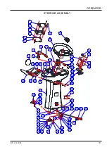
Page 39: ...ICE iS1100L 37 OPERATOR STEERING ASSEMBLY ...

Page 40: ...asher 8 4 10 1021816 Screw RHM M8X16 SST 4 11 7000051 Lever Shaft 2 12 7000053 Support Main Brush Shaft 4 13 1521640 Socket Head M6X40 SST 8 14 1645425 Elastic Pin 4X25 4 15 1421334 Washer Plain 19X 34X3 4 16 1421612 Washer Plain 6X 12X1 6 8 17 1123608 Nut Lock SS M6 8 18 7000051 1 Hex Head Screw SST 2 19 1123507 Nut Lock SS M5 2 20 7000412 Micro Switch 2 21 1021430 Screw RHM M4X30 SST 4 22 102181...

Page 41: ...ICE iS1100L 39 OPERATOR STEERING ASSEMBLY ...

Page 42: ...ver 2 17 4010316 ICE Logo 1 18 1221516 Screw PH M5X16 SST 3 19 1421510 Washer Plain 5 3X 10X1 3 20 1421409 Washer Plain 4 3X 9X0 8 3 21 1321110 Screw ST3 5X10 3 22 8133602 Cover Led Lighter 1 23 8133601 Support Led Lighter 1 24 8133610 Led Lighter 1 25 7000407 Cover Steering Column 1 26 7000116 Return Lever Side Brush 1 27 7000115 Spacer 1 28 1621624 Washer Plain 6 6X 22X2 1 29 1422616 Washer Lock...

Page 43: ... 43 1121008 Nut SS M10 2 44 7000173 Bar 1 45 7000294 Joint head 1 46 1521625 Socket Head M6X25 SST 3 47 7000707 Serial Decal 1 48 8134768 RFID PCB 1 49 8134769 Box PCB 1 50 7000423 Decal Main brush 1 51 7000427 Decal Side brush 1 52 7000424 Support Switch 1 53 1222305 Screw FH M3X5 SST 2 54 6210503 Switch 1 55 7000428 Cover Steering Wheel 1 ...

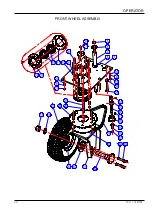
Page 44: ...42 ICE iS1100L OPERATOR FRONT WHEEL ASSEMBLY ...

Page 45: ...Head M5X12 SST 2 15 1021825 Screw RHM M8X25 SST 9 16 7000093 Crown 1 17 7000198 Front Wheel 1 18 1421330 Washer Plain 21X 37X3 1 19 1123020 Nut Lock SS M20 1 20 7000104 Flange 1 21 7000087 Support Front Wheel 1 22 7000105 Shaft Front Wheel 1 23 1521025 Socket Head M10X25 SST 4 24 1422026 Washer Lock Ø10 4 25 7000092 Plate 1 26 7000110 Chain 1 27 1021616 Screw RHM M6X16 SST 1 28 1422616 Washer Lock...

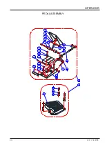
Page 46: ...44 ICE iS1100L OPERATOR PEDAL ASSEMBLY ...

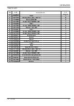
Page 47: ...r 1 9 1222690 Screw RHM M6X90 SST 1 10 1521612 Socket Head M6X12 SST 4 11 7000211 Pedal Support 1 12 7000217 Spring 1 13 7000213 Spacer 1 14 7000508 Cable Front Skirt Lift up 1 15 7000219 Lever 1 16 7000507 Clips 1 17 7000162 Speed Control Pedal 1 18 1411816 Washer Plain 8X 16X1 6 3 19 1422821 Washer Lock Ø8 3 20 1521820 Socket Head M8X20 SST 3 21 7000210 Front Skirt Rainsing Pedal Kit 1 22 700016...

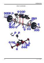
Page 48: ...46 ICE iS1100L OPERATOR DRIVE ASSEMBLY ...

Page 49: ...012 Nut Lock SS M10 4 11 1411020 Washer Plain 10X 20X2 4 12 1421612 Washer Plain 6X 12X1 6 10 13 1422616 Washer Lock Ø6 18 14 1021620 Screw RHM M6X20 SST 10 15 7000037 Support Transaxle 1 16 7000188 Ball Bearing with Flange 2 17 1021616 Screw RHM M6X16 SST 8 18 7000040 Bracket Transaxle 1 19 7000327A Electric brake kit for CCL motor 7000325A 1 20 7000325 1 Carbon brushes for CCL motor 7000325A 4 2...

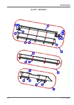
Page 50: ...48 ICE iS1100L OPERATOR SKIRTS ASSEMBLY ...

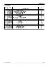
Page 51: ...123608 Nut Lock SS M6 16 5 7000128 Plate Front Skirt 1 6 7000127 Front Skirt 1 7 1513626 Countersunk Hex Screw M6X25 1 8 1421612 Washer Plain 6X 12X1 6 1 9 7000147 Spring 1 10 7000130 Rear Skirt 1 11 7000131 Plate Rear Skirt 1 12 7000134 Side Skirt 1 13 7000135 Plate Side Skirt 2 14 7000122 Front Skirt Assembly 1 15 7000129 Rear Skirt Assembly 1 16 7000136 Left Skirt Assembly 1 ...

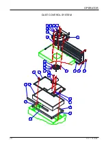
Page 52: ...50 ICE iS1100L OPERATOR DUST CONTROL SYSTEM ...

Page 53: ...6 7000158 Cover 1 7 7000159A Vacuum Fan 1 8 7000160 Screen Protection 1 9 1021616 Screw RHM M6X16 SST 4 10 7000195A Filter Shaker Motor 1 11 7000042 Filter Frame 1 12 7000180 Knob 2 13 7000048 Panel Filter 1 14 7000291 Gasket 1 15 7000047 Gasket Short 2 16 7000046 Gasket Long 2 17 7000265 Gasket 1 18 7000264 Rear Cover 1 19 7000175 Knob 4 20 7000164 Gasket 1 21 1121605 Nut SS M6 4 22 1421612 Washe...

Page 54: ...52 ICE iS1100L OPERATOR HOPPER ASSEMBLY ...

Page 55: ...her Plain 6X 18X1 6 4 9 1123608 Nut Lock SS M6 4 10 7000181 Latch 1 11 7000140 Cap 2 12 1521612 Socket Head M6X12 SST 2 13 1422616 Washer Lock Ø6 2 14 7000138 Hopper 1 15 1022890 Screw RHM M8X90 SST 2 16 7000141 Plate 1 17 7000232 Handle Assembly 2 18 1021516 Screw RHM M5X16 SST 8 19 1123507 Nut Lock SS M5 8 20 1421510 Washer Plain 5 3X 10X1 8 21 7000238 Left Bocket 1 22 7000236 Right Bocket 1 23 ...

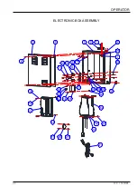
Page 56: ...54 ICE iS1100L OPERATOR ELECTRONIC BOX ASSEMBLY ...

Page 57: ...rol Unit 1 18 1021535 Screw RHM M5X35 SST 2 19 1021314 Screw RHM M3X14 SST 2 20 8310708A Buzzer 1 21 1123305 Nut Lock SS M3 2 22 1021516 Screw RHM M5X16 SST 4 23 8134610 Li_ion Battery Charge 110V 16A 1 24 1621624 Washer Plain 6 6X 22X2 4 25 1422616 Washer Lock Ø6 4 26 1021616 Screw RHM M6X16 SST 4 27 7000321 Snap Bushing 2 28 1021610 Screw RHM M6X10 SST 3 29 1421409 Washer Plain 4 3X 9X0 8 2 30 7...

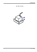
Page 58: ...56 ICE iS1100L OPERATOR BATTERY GROUP ...

Page 59: ...ICE iS1100L 57 OPERATOR PARTS LIST DIA NO PART NUMBER DESCRIPTION NO REQ D 1 7000169 Battery Container 1 2 N240350 Lithium ion Battery 24VDC 100Ah 1 ...

Page 60: ...58 ICE iS1100L OPERATOR ACCESSORIES ...

Page 61: ...oof Protection 1 6 1022845 Screw RHM M8X45 SST 4 7 7000618 Bracket Front 2 8 1421518 Washer Plain 5X 18X2 2 9 1422513 Washer Lock Ø5 2 10 7000413A Led Worklamp 1 11 7000114 Support Led Worklamp 1 12 7000148 Bracket 1 13 1421824 Washer Plain 8X 24X2 1 14 1422821 Washer Lock Ø8 1 15 1521820 Socket Head M8X20 SST 1 16 7000610 Kit Protection Roof Optional 1 17 7000630 Kit Working Light 1 18 7000619 Ca...

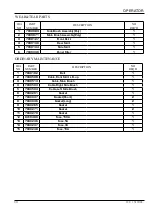
Page 62: ...el Filter 1 ORDINARY MAINTENANCE DIA NO PART NUMBER DESCRIPTION NO REQ D 1 7000192 Belt 1 2 7000508 Cable Front Skirt Lift up 1 3 7000513 Cable Main Brush 1 4 7000503 Cable Right Side Brush 1 5 7000504 Cable Left Side Brush 1 6 7000291 Gasket 1 7 7000047 Gasket Short 2 8 7000046 Gasket Long 2 9 7000265 Gasket 1 10 7000271 Gasket 2 11 7000270 Gasket 1 12 8310480 Fuse 150A 1 13 7000246 Fuse 5A 1 14 ...

Page 63: ......

Reviews: