


54
TROUBLESHOOTING
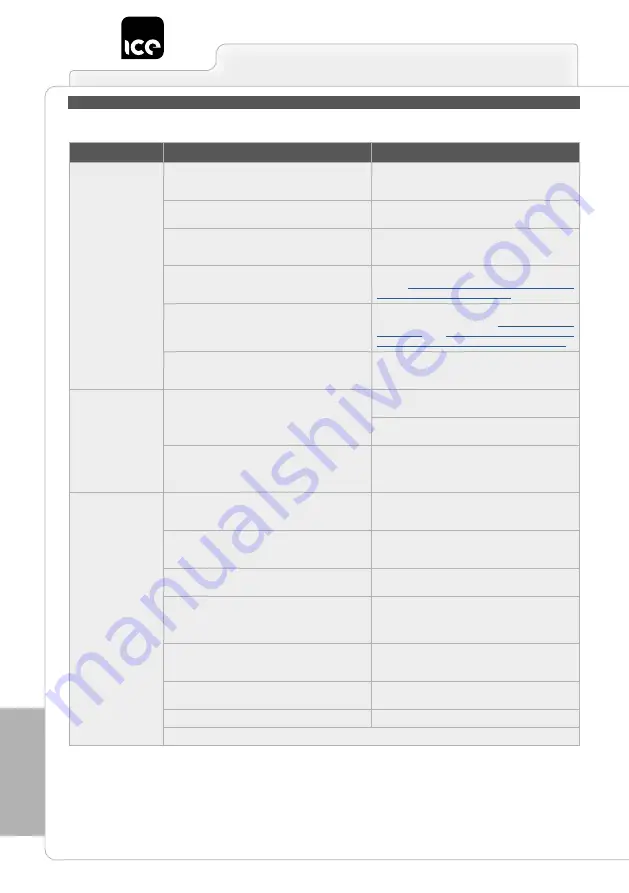
TROUBLESHOOTING
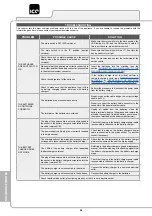
This chapter lists the most common problems linked with the use of the appliance. If you are unable to resolve the problems with the
information given here, please contact your nearest assistance centre.
PROBLEM
POSSIBLE CAUSE
SOLUTION
THE APPLIANCE
DOES NOT SWITCH
ON
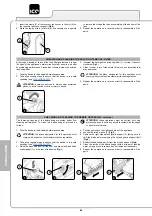
The main switch is OFF (50D versions).
Make sure the main switch is in the work position, the
LED inside it is ON, and the ON symbol is visible. If
this is not the case, press the main switch.
The main switch is in the "0" position (traction
versions).
Make sure that the main switch is at "I", if not turn the
key a quarter turn to right.
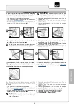
Check there are no alarm messages on the control
display when the appliance is switched on (traction
versions).
Stop the machine and contact the technician at the
service centre.
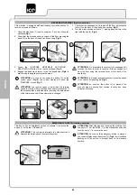
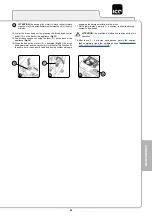
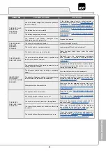
Make sure that the batteries are correctly connected to
each other and that the battery connector is connected
to the electrical system connector.
Insert the batteries into the machine (see the
section
CONNECTING THE BATTERIES TO THE
”).
Check the charge level of the batteries.
If the battery charge level is critical, perform a
complete charging cycle (read “
” or “
(VERSIONS WITH BUILT-IN BATTERY CHARGER)
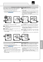
Check to make sure that the appliance is not still in
its battery charging phase (versions with battery
charger).
Perform the procedure to disconnect the power cable
from the battery charger.
THE BATTERIES
DO NOT WORK
CORRECTLY
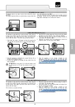
The batteries are not connected correctly
Properly connect the cable bridge, the output voltage
should be 24V.
Properly connect the battery cable connector to the
connector of the general system cable.
The terminals of the batteries are oxidized.
Unplug all cables from the batteries, clean the
battery terminals, apply a little grease and restore the
electrical connections (read the battery user manual,
the manual provided by the battery manufacturer).
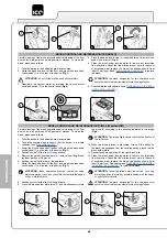
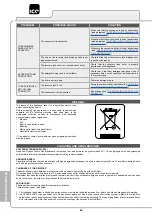
THE BATTERY
CHARGER DOES
NOT WORK
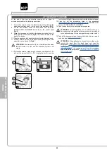
The plug of the power cable is not correctly inserted in
the socket in the battery charger incorporated into the
machine (versions CB).
Check that the plug in the battery charger power cable
is connected to the socket in the battery charger.
The power supply cable plug is not correctly inserted
in the mains socket.
Check that the plug on the battery charger's power
cable is connected to the mains socket. Try another
socket if necessary.
The characteristics of the mains power supply do not
correspond to those required by the battery charger.
Check that the characteristics in the battery charger
plate are the same as those of the mains supply.
The LEDs of the battery charger blink repeatedly
(battery charger versions).
Referring to the battery charger use and maintenance
manual, check the meaning of the flashing signals that
the battery charger emits dung the battery recharge
stage.
The plug of the power cable is not correctly inserted in
the socket in the battery charger incorporated into the
machine (versions CB).
Check that the plug in the battery charger power cable
is connected to the socket in the battery charger.
The battery charger is not connected to the mains.
Connect the battery charger to a powered electrical
outlet.
The battery charger is not connected to the batteries.
Connect the battery charger to the batteries.
Check that the mains outlet is functioning properly, or that it is not a daytime socket.


