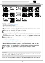
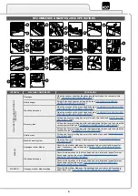
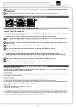


ASSEMBLING THE SQUEEGEE BODY
For packaging reasons, the squeegee body comes disassembled from the machine. In order to mount it on the squeegee support, do the
following:
1. Make sure the machine is in a safe condition (read “
2. Raise the squeegee body and turn the squeegee control lever (4) in the direction of the arrow (
Fig.4
). The lever is located on the back of the
machine.
CAUTION:
these operations must be carried out using protective gloves to avoid any possible contact with the edges or tips of metal
objects.
3. Unscrew the knobs (15) in the squeegee body pre-assembly (
Fig.18
).
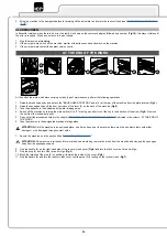
4. First of all, insert the left-hand pin (16) on the squeegee body in the left slit (17) in the squeegee support (
Fig.19
), so that the bushing (18)
adheres to the walls of the slit.
5.
Tighten the knobs (15) to fix the squeegee body to the support.
6. Repeat the same operation for the right pin.
7. Insert the vacuum tube (19) in the sleeve (20) in the squeegee body (
Fig.20
).
N.B.:
the tube must be positioned behind the squeegee lifting chain.
N.B.:
Although the squeegee comes pre-adjusted, it is nevertheless recommended to read the section titled “ADJUSTING THE
SQUEEGEE BODY'S RUBBER BLADES”.
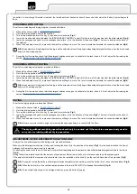
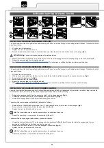
INSERTING WATER SYSTEM FILTER
Before using the machine for the first time the water system filter needs to be reset, for shipping reasons the filter cartridge and the cap have
been removed. To insert the filter cartridge in the water system filter body proceed as follows:
1. Take the machine to the maintenance area.
2. Make sure the machine has been secured (see the section titled “
”).
CAUTION:
users are advised to always wear protective gloves, to avoid the risk of serious injury to hands.
3.
Insert the filter cartridge (21) in the housing on the cap (22) (
Fig.21
).
N.B.:
The O-ring gasket in the filter cartridge should be inserted into its seat in the cap.
4.
Go to the right-hand side of the machine, screw on the cap (22) to the body of the detergent solution filter (23) (
Fig.22
).
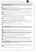
FILLING THE SOLUTION TANK WITH WATER
Before filling the solution tank, carry out the following steps:
1.
Take the machine to the usual place for filling the solution tank.
2. Perform the procedure for securing the machine ( see the section titled “
”).
3. Check the solution tank drainage cap (24) (on the rear right-hand side of the machine) is tight. If it isn't, turn it clockwise (
Fig.23
).
4.
Check the water system filter cap (22) (on the rear right-hand side of the machine) is tight. If it isn't, turn it clockwise (
Fig.22
).
The solution tank can be filled with water in three different ways:
•
Remove the cap/measuring device (25) (
Fig. 24
) and fill the solution tank by means of a rubber hose or a bucket.
•
When using the filler hose (26) (
Fig.25
), which supports the water hose on its own, remember to remove the cap/measuring device (25) in
order to allow the air to vent properly.
•
Using the optional automatic clean water refill system, connect the female connector on the tube to the male connector (27) on the machine
(
Fig. 26
); before connecting the tube, remember to remove the cap (28) and the cap/measuring device (25) to enable the air to be vented.
5. Fill with clean water, at a temperature not higher than 50°C and not lower than 10°C. The amount inside the tank can be seen by means of
the level tube (29) (
Fig.27
) on the rear of the machine.
DETERGENT SOLUTION
After filling the solution tank with clean water add the liquid detergent to the tank in the concentration and manner indicated on the detergent
manufacturer's label. To prevent the formation of an excessive amount of foam that could damage the vacuum motor, use the minimum
percentage of detergent required.
CAUTION:
protective gloves should always be worn before handling detergents or acidic or alkaline solutions, to avoid serious injury to the
hands.
CAUTION:
Always use detergents whose manufacturer's label indicates their suitability for scrubbing machines. Do not use acid or
alkaline products or solvents without this indication.
15