background image

DRYING

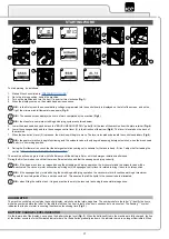
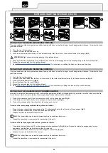
To perform a drying program, proceed as follows:

1.  Make all the checks listed in “

PREPARING TO WORK

”.

2.  Go to the driving position, behind the machine.

3.  Turn on the machine and turn the key (1) a quarter turn clockwise (

Fig.1

). 

4.  Lower the squeegee body and turn the squeegee control lever (3) in the direction of the arrow (

Fig.5

). The lever is located on the back of 

the machine.

5.  When the dead man's lever (4) is pressed, the machine will begin to move. The lever is located underneath the control handlebars (

Fig.6

).

N.B.:

 the vacuum motor will only begin to work when the squeegee body is in contact with the floor.

The drying without scrubbing operation should only be carried out if the machine was previously used to 

carry out a scrubbing without drying operation.

ADJUSTMENT OF THE DETERGENT SOLUTION FLOW

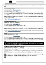
To adjust the flow of detergent solution during work, proceed as follows:

Make sure the detergent solution tap is fully open, rotating the knob (5) in the direction of the arrow (

Fig.7

). As the knob is rotated, the flow of 

detergent in the machine water circuit is increased.

On pushing the dead man's lever (4) the brush motor will start operating and the solenoid valve will distribute detergent solution to the brush 

(

Fig.6

).

During the first few meters check that the amount of solution is sufficient to wet the floor, but not excessive to exit the splash guard.

If the amount of solution that comes out is not suitable, it can be controlled via the knob (5) on the rear left-hand side of the machine (

Fig.7

).

N.B.:

 If you wish to stop the delivery of detergent solution completely when working, press the button (6) on the control handlebars (

Fig.8

).

N.B.:

 When the button (6) on the control display is pressed, the word “H2O STOP” will appear intermittently(

Fig.9

).

N.B.:

 To reactivate the delivery of the detergent solution, press the button (6) again.

SCRUBBING WITHOUT DRYING

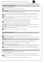
To perform a scrubbing only program, proceed as follows:

1.  Make all the checks listed in “

PREPARING TO WORK

”.

2.  Go to the driving position, behind the machine.

3.  Turn on the machine and turn the key (1) a quarter turn clockwise (

Fig.1

). 

4.  Lower the brush head body and detach the "BRUSH HEAD CONTROL" pedal (2) at the rear of the machine from the plate retainer (

Fig.4

).

5.  When the dead man's lever (4) is pressed, the machine will begin to move. The lever is located underneath the control handlebars (

Fig.6

).

N.B.:

 the gearmotor will only begin functioning, and the solenoid valve will only begin dispensing detergent solution, when the brush head 

body is in its working position.

6. 

During the first few metres, check that the detergent solution coming out is suitable for the task in hand. If it isn't, adjust it after reading the 

section "

REGULATING THE DETERGENT SOLUTION

".

SCRUBBING WITH DRYING

To perform a scrubbing and drying program, proceed as follows:

1.  Make all the checks listed in “

PREPARING TO WORK

”.

2.  Go to the driving position, behind the machine.

3.  Turn on the machine and turn the key (1) a quarter turn clockwise (

Fig.1

). 

4.  Lower the brush head body and detach the "BRUSH HEAD CONTROL" pedal (2) at the rear of the machine from the plate retainer (

Fig.4

).

5.  Lower the squeegee body and turn the squeegee control lever (3) in the direction of the arrow (

Fig.5

). The lever is located on the back of 

the machine.

6.  When the dead man's lever (4) is pressed, the machine will begin to move. The lever is located underneath the control handlebars (

Fig.6

).

N.B.:

 the gearmotor will only begin functioning, and the solenoid valve will only begin dispensing detergent solution, when the brush head 

body is in its working position.

7. 

During the first few metres, check that the detergent solution coming out is suitable for the task in hand. If it isn't, adjust it after reading the 

section "

REGULATING THE DETERGENT SOLUTION

".

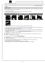
the battery “critical charge” threshold is reached, the last indicator bar flashes for about 20 seconds, after which the “battery” symbol begins to 

flash.

18

Summary of Contents for SCRUB 80 D

Page 1: ...SCRUB 80 D SCRUBBING MACHINES USE AND MAINTENANCE MANUAL ORIGINAL INSTRUCTIONS DOC 10083798 Ver AA 12 2018...

Page 2: ......

Page 3: ...pedal 14 Main key switch 15 Vacuum tube 16 Solution tank drainage cap 17 Squeegee body support 18 Squeegee body 19 Water flow adjustment tap 20 Front headlights optional 21 Solution tank filler cap m...

Page 4: ...8 DISPOSAL 9 SYMBOLS USED ON THE MACHINE 10 SYMBOLS PRESENT ON THE REGISTRATION PLATE 10 SYMBOLS PRINTED ON THE MACHINE 10 LABELS USED ON THE MACHINE 10 PREPARATION OF MACHINE 11 HANDLING THE PACKAGED...

Page 5: ...ING THE SQUEEGEE BODY 22 CLEANING THE DEBRIS HOPPER SWEEPING VERSION 22 CLEANING THE BRUSH HEAD BRUSHES SCRUBBING VERSION 22 CLEANING THE BRUSH HEAD BRUSHES SWEEPING VERSION 22 DRAINING THE RECOVERY T...

Page 6: ...efully read the sections preceded by this symbol meticulously following the instructions indicated for the safety of the operator and the device Danger symbol corrosive substances The operator should...

Page 7: ...model the version and the serial number written on the relevant plate TECHNICAL DESCRIPTION The Scrub 80D is a floor scrubbing machine that can work on various types of floor and dirt thanks to the me...

Page 8: ...ength width 3 height mm 1497 701 1093 1514 795 1093 1542 878 1093 1471 733 1093 Battery compartment dimensions length width useful height mm 524 396 320 524 396 320 524 396 320 524 396 320 Recommended...

Page 9: ...24 300 Maximum forward speed in transport mode mph 3 04 3 04 3 04 3 04 Vacuum motor voltage nominal power rating V W 24 422 24 422 24 422 24 422 Vacuum on vacuum head mBar 112 112 112 112 Maximum sol...

Page 10: ...the correct position of the brush head control pedal in order to activate the extra pressure function Squeegee body working position symbol Located on the rear part of the machine to indicate the sque...

Page 11: ...NE HANDLING THE PACKAGED MACHINE The machine is contained in specific packaging and since the packaging elements plastic bags staples etc are a potential source of danger they should not be left withi...

Page 12: ...pedal 3 fully and then move it towards the right hand side of the machine Fig 3 4 Raise the squeegee body and turn the squeegee control lever 4 in the direction of the arrow Fig 4 The lever is located...

Page 13: ...by an unauthorized technician RECHARGING THE BATTERIES The batteries must be charged prior to first use and whenever they no longer provide sufficient power ATTENTION to avoid any permanent damage to...

Page 14: ...machine see the section titled SECURING THE MACHINE CAUTION users are advised to always wear protective gloves to avoid the risk of serious injury to hands 2 Raise the brush head body and fully depres...

Page 15: ...achine screw on the cap 22 to the body of the detergent solution filter 23 Fig 22 FILLING THE SOLUTION TANK WITH WATER Before filling the solution tank carry out the following steps 1 Take the machine...

Page 16: ...EEPING VERSION 5 Check that the machine is off if this is not the case turn the key 2 a quarter turn anti clockwise Fig 2 Remove the key from the instrument panel 6 Grip the handle 3 on the right hand...

Page 17: ...will now begin to work with full efficiency until the battery is flat or until the detergent solution has finished During the first few metres check that there is sufficient solution and that the squ...

Page 18: ...HOUT DRYING To perform a scrubbing only program proceed as follows 1 Make all the checks listed in PREPARING TO WORK 2 Go to the driving position behind the machine 3 Turn on the machine and turn the...

Page 19: ...rs again BATTERY DISCONNECT SWITCH If any serious problems are encountered during the work operations press the battery disconnect button 8 on the electrical system carter Fig 14 CAUTION This command...

Page 20: ...tion titled SECURING THE MACHINE ATTENTION if the machine is left unused for more than one whole day remove the brush from the brush head body and the squeegee body from the squeegee support 8 Grip th...

Page 21: ...vacuum tube see CLEANING THE VACUUM TUBE Solution tank At the end of every working day empty the solution tank read EMPTYING THE SOLUTION TANK WEEKLY Machine water system Clean the filter in the mach...

Page 22: ...EEGEE BODY RUBBER BLADES CLEANING THE DEBRIS HOPPER SWEEPING VERSION To clean the debris hopper proceed as follows 1 Use the moulded handle to extract the debris hopper 8 Fig 7 and empty it N B The pl...

Page 23: ...ssary use a spatula to remove any sludge that may have accumulated at the bottom of the tank 9 Repeat the operations in reverse order to reassemble all the parts 7 See INSTALLING THE BRUSH SWEEPING VE...

Page 24: ...or instructions on refitting the brushes in the brush head body REPLACING THE SQUEEGEE BODY RUBBER BLADES Ensuring the integrity of the squeegee body s rubber blades guarantees better floor cleaning a...

Page 25: ...floor 5 Once the adjustment has been completed tighten the knob 5 N B Before using the machine remember to adjust the squeegee body see the section titled ADJUSTING THE SQUEEGEE BODY S RUBBER BLADES...

Page 26: ...electrical system connector Connect the batteries correctly inside the machine see INSERTING THE BATTERIES IN THE MACHINE Check the charge level of the batteries If the battery charge level is critic...

Page 27: ...are excessively worn Check the wear of the brush and if necessary replace it see REPLACING THE BRUSH SCRUBBING VERSION or REPLACING THE BRUSH SWEEPING VERSION THE SQUEEGEE DOES NOT DRY PERFECTLY The v...

Page 28: ...2 2005 AC 2005 EN 61000 6 3 2007 A1 2011 AC 2012 EN 62233 2008 AC 2008 The person authorised to compile the technical file Mr Mark Bresnihan Sauber House Unit 3 Rushington Business Park Chapel Lane To...

Page 29: ...3 2007 A1 2011 AC 2012 EN 61000 3 2 2014 EN 61000 3 3 2013 EN 55014 1 2006 A1 2009 A2 2011 EN 55014 2 2015 EN 62233 2008 AC 2008 The person authorised to compile the technical file Mr Mark Bresnihan...

Page 30: ...30...

Page 31: ......

Page 32: ...Industrial Cleaning Equipment Ltd Sauber House Unit 3 Rushington Business Park Chapel Lane Totton Hampshire SO40 9AH Service 0800 389 3869 Facsmile 023 8042 8318 Email info ice clean com...

Reviews: