60
X’s 6
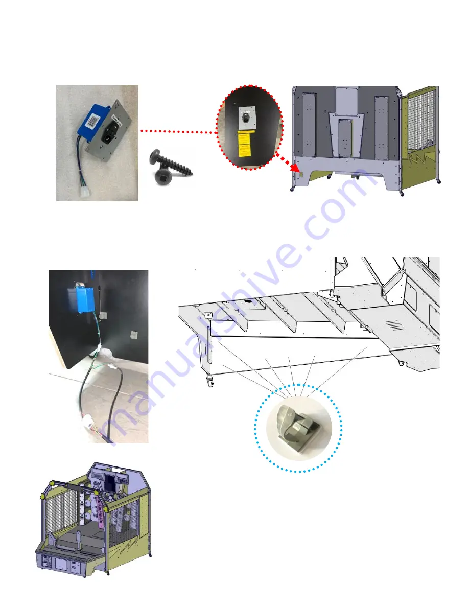
STEP 62:
Install the power inlet module with six AA0655 screws. Also apply DECALS from parts box
(“CAUTION”, “WARNING”, “SUITABLE”) .
E08639 HARNESS
CLAMP
Underside of Game
Step 63:
Install wire clips along the right side of the cabinet. Run the AC harness from the front to back using
the wire clips to secure it to the cabinet.
Completed chapter 8.
Use the 6 holes with pilot holes that match the metal plate.
Summary of Contents for DB1200X
Page 7: ...7 Assembly for Steps 1 8 Chapter 1...
Page 16: ...16 Assembly for Steps 9 16 Chapter 2...
Page 22: ...22 Assembly for Steps 17 22 Chapter 3...
Page 28: ...28 Assembly for Steps 23 26 Chapter 4...
Page 33: ...33 Assembly for Steps 27 43 Chapter 5...
Page 43: ...43 Assembly for Steps 44 51 Chapter 6...
Page 48: ...48 Assembly for Steps 52 59 Chapter 7...
Page 53: ...53 STEP 57 Tower harnesses Insert cables from each tower assembly into the bottom holes B...
Page 75: ...75 Tower Covers Part Numbers...
Page 76: ...76 DECAL PART NUMBERS...
Page 82: ...82 DB3277X ball gate Assembly NS1022 P802 black NS1022 P509 blue ZS2015X Actuator...


