9
Rev. 6
*Verify voltage with model*
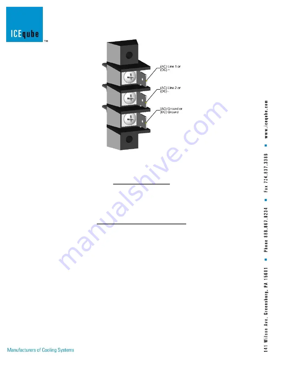
Figure 5: Power Terminal Block (optional)
Operating Your System
Once the Ice Qube TMS has been installed onto the enclosure and the power cable has been attached to a
properly grounded electrical connection with adequate voltage and current supply, the unit is ready for
operation. As soon as electrical power is supplied to the Ice Qube TMS, both fans will begin to move air
through the MSCCT heat exchanger.
Fan Speed Controller (Ord Loc Only)
Version 1.4
Ice Qube offers an optional fan speed controller that requires an input voltage in the range of 24 through
250 AC or DC. Check the model label for the proper voltage requirements of the heat exchanger. For either
AC or DC voltages, (+) is positive or “hot” and (-) is negative or “neutral”, the power connection is polarity
sensitive. Be careful when handling or adjusting the controller as all components and circuitry are at line
voltage except for the alarm outputs which are dry contacts.
When power is applied to the heat exchanger, the fan speed controller will automatically sequence through
a diagnostic procedure that will check the operation of the fans and the optional alarm relay. Following s
the test sequence.
Test Mode
FAN 1 comes ON. If PWM type, FAN 1 starts at minimum speed and ramps up to full speed over a 25
second period with its LED blinking faster during the period. Upon achieving full speed, fan will operate at
full speed for 15 seconds. Then FAN 1 goes OFF. LED 1 pulses once per 2 seconds when the fan is off.
If single speed, the fan will operate for forty seconds, LED ON when FAN is ON. Then FAN 1 goes OFF.
LED 1 pulses once per 2 seconds. Pause for 3 seconds.
Summary of Contents for IQ700HE
Page 8: ...8 Rev 6 Figure 3 Terminal Cover Figure 4 Terminal Block optional ...
Page 13: ...13 Schematic Wiring Diagram Figure 6 ...
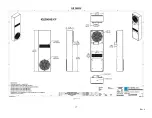
Page 14: ...14 Rev 6 Specification Drawings IQ700HE Figure 7 ...
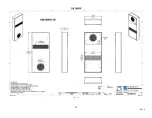
Page 15: ...15 Rev 6 IQ800HE Figure 8 ...
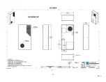
Page 16: ...16 Rev 6 IQ900HE Figure 9 ...
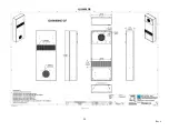
Page 17: ...17 Rev 6 IQ2200HE Figure 10 ...
Page 18: ...18 Rev 6 IQ6100HE Figure 11 ...
Page 19: ...19 Rev 6 IQ7400HE Figure 12 ...
Page 20: ...20 Rev 6 IQ10000HE Figure 13 ...
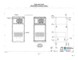
Page 22: ...22 Rev 6 IQ900HE Gasket and Cutout Figure 15 ...
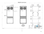
Page 23: ...23 Rev 6 IQ2200HE Gasket and Cutout Figure 16 ...
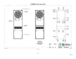
Page 24: ...24 Rev 6 IQ6100HE Gasket and Cutout Figure 17 ...
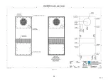
Page 25: ...25 Rev 6 IQ7400HE Gasket and Cutout Figure 18 ...
Page 26: ...26 Rev 6 IQ10000HE Gasket and Cutout Figure 19 ...
Page 29: ...29 Rev 6 Notes ...


