background image

   E N G L IS H 


2.  Installation procedure 


The ice-maker shall be lifted using the four shackles fixed on its base plate (for small-sized machine) or on its top (for large-sized 
machine) and shall be laid down slowly on the support or ice storage bin that has been put in place. 
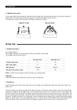
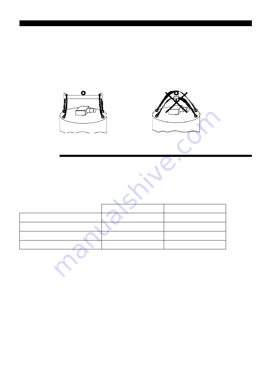
For large-sized ice-maker, the correct steel cable lifting is as shown in this figure. 


CORRECT LIFTING 

WRONG LIFTING 


OPERATION 


1. Preliminary Checks 


a) Is machine levelled? 
b) Are voltage and frequency of mains supply the same as indicated on rating plate? 
c) Is drainage system working properly? 


Minimum value 

Maximum value 

Ambient temperature 

5º 

40º 

Water temperature 

5º 

35º 

Water pressure 

1,5kg/cm2 

5kg/cm2 

Desviation from voltage rating 

-10% 

6% 

NOTE: 

To install a pressure reducer If water inlet pressure is more than 6 Bar. 


ATENTION: 

Check that voltage and mains frequency is the same as in the rating plate. 


2.  Starting up 


Open  feed  water  valve  and  fill  up  the  water  tank,  and  the  floating  valve  automatically  closes  when  water  level  reaches  the 
spillover port. 


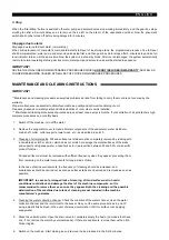
During trial operation, pneumatic mains switch (K1) shall be turned to 

“ON”, then the power indicator on the panel of electrical box 

(see Figure 5). Switch on the Start/Stop button on the electrical cabinet to enable the ice-maker to enter a 3-minute-delay state 
(indicator of Start Delay blinks) which is followed by the automatic start of gear box and water pump by the control system,  and 
then the machine goes into operation. Observation shall be conducted at this time to verify that (1) ice blade is rotating in correct 
direction or the shaft and rotation is in normal status; (2) water dispensing disc is aligned with the red mark and water-dispensing 
pipes have normal output. In case above-stated items are all in normal operation, the Start/Stop button shall be switched off to 
stop the ice machine. (3) Ice production stage: Start refrigeration system and open return air valve and Freon feed valve. 

Summary of Contents for SCL 400

Page 1: ...Technical Manual Manual T cnico...

Page 2: ...L 15T SC 15TN TABLE OF CONTENTS 1 INTRODUCTION 4 Warnings 4 Overview 5 Wiring Diagram 6 2 SPECIFICATIONS 8 Production Tables 11 3 DELIVERY AND UNPACKING 13 4 INSTALLATION 13 Recommended Placement of U...

Page 3: ...RE cleaning or maintaining the equipment Do not attempt to install service or modify this machine Improper use by other than specially trained technicians is extremely dangerous and may result in a fi...

Page 4: ...machines The ice machine system is of vertical internal ice scraping type The machine is equipped with an electric box with different protections and status lights namely 1 Ice level 2 Water pressure...

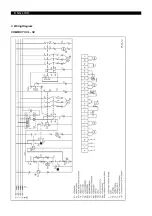
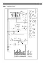
Page 5: ...E N G L IS H 3 Wiring Diagram COMPACT SCL SC...

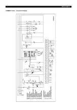
Page 6: ...E N G L IS H COMPACT SCL SC with V f driver...

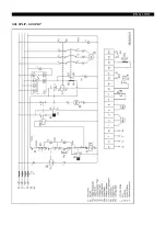
Page 7: ...SCL SPLIT SC SPLIT E N G L IS H...

Page 8: ...E N G L IS H SCL SPLIT SC SPLIT with V f driver...

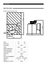
Page 9: ...ION 0 4T 0 6T REFRIGERANT R449A POWER 1425W 2350W AMBIENT TEMPERATURE 25oC WATER TEMPERATURE 16oC WATER CONSUMPTION 17 L H 25 L H WATER INLET 3 4 GAS DRAIN 21mm ELECTRICAL REQUIREMENTS 380 50Hz 3N DIM...

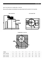
Page 10: ...ion measurement and size of ice outlet of 1 3 ton ice maker PIPE CONNECTION PIPE CONNECTION DIMENSIONS OF ICE OUTLE MODEL A B C D E L W H SCL 1T SC 1TN 150 750 198 490 310 1050 850 870 480 SCL 2T SC 2...

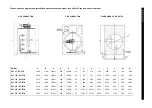
Page 11: ...1850 1150 1000 1 250 1050 1 50 775 575 1600 1500 650 150 900 SCL 15T SC 15TN 2510 1800 1230 1 285 1700 1 50 900 900 2200 1950 960 250 1580 SCL 20T SC 20TN 2510 1800 1230 1 285 1700 1 50 900 900 2400...

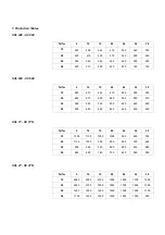
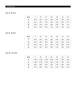
Page 12: ...0 25 640 610 600 580 550 530 510 30 560 540 530 500 480 460 450 38 500 490 480 460 440 430 400 SCL 1T SC 1TN Ta Tw 5 10 15 20 26 32 38 10 1200 1100 1050 1000 900 830 750 25 1100 1000 950 900 850 780 6...

Page 13: ...1580 SCL 5T SC 5TN Ta Tw 5 10 15 20 26 32 38 10 5600 5500 5200 5000 4600 4200 3800 25 5400 5300 5000 4600 4300 3900 3400 30 4900 4600 4300 3900 3400 3000 2900 38 4400 4300 4000 3600 3200 2900 2500 SC...

Page 14: ...N REACH OF CHILDREN INSTALLATION 1 Recommended Placement of Unit Sockets and wiring must comply with local standards for electrical appliances and requirements set forth on the rating plate of the mac...

Page 15: ...rating plate 2 Starting up Open feed water valve and fill up the water tank and the floating valve automatically closes when water level reaches the spillover port During trial operation pneumatic mai...

Page 16: ...urn off the water 2 Remove the evaporator cover to clean all metal components of the evaporator water distributor main shaft cutter cutter supports lower cross etc as described in point 3 3 Cleaning o...

Page 17: ...or low water level alarm Low water pressure Clean or replace filters Ice production decreases Regulation valve partially blocked or improperly adjusted Adjust or replace float valve Low water level of...

Page 18: ......

Page 19: ......
Reviews: