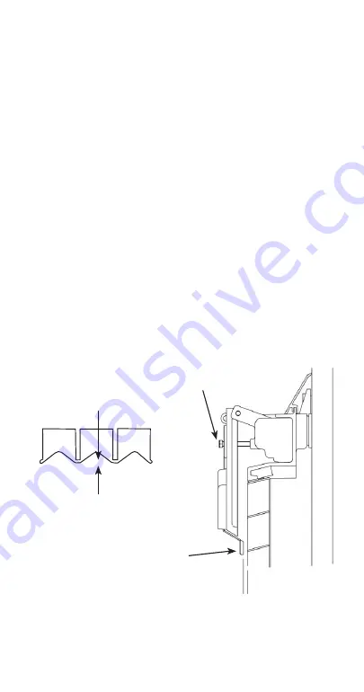
Ice Thickness Check
The ice thickness probe is factory-set to maintain the ice
bridge thickness at 1/8 inch.
NOTE: Make sure the water curtain is in place when
performing this check. It prevents water from splashing
out of the water trough. Remove the curtain to make an
adjustment, then replace immediately after the
adjustment is made.
1. Inspect the bridge connecting the cubes. It should
be about 1/8 in. (3 mm) thick.
2. If adjustment is necessary, turn the ice thickness
probe adjustment screw clockwise to increase
bridge thickness or counterclockwise to decrease
bridge thickness. Set a 1/4" gap between the ice
thickness probe and evaporator as a starting point.
Then adjust to achieve 1/8" ice thickness.
3. Make sure the ice thickness probe wire and the
bracket do not restrict movement of the probe.
1/8" (3 mm)
ICE BRIDGE THICKNESS
ICE THICKNESS ADJUSTMENT
ADJUSTING
SCREW
PLACE
1
/
4
" DRILL BIT
HERE TO SET INTIAL GAP
108
Summary of Contents for IM Series
Page 1: ...Revision Date 1 24 22 IM Series Air Water Remote Ice Machines Technician s Handbook ...
Page 2: ......
Page 3: ...THIS PAGE INTENTIONALLY LEFT BLANK ...
Page 9: ...THIS PAGE INTENTIONALLY LEFT BLANK ...
Page 15: ...THIS PAGE INTENTIONALLY LEFT BLANK 14 ...
Page 17: ...How to Read a Serial Number Full Serial Number 16 ...
Page 35: ...THIS PAGE INTENTIONALL Y LEFT BLANK 34 ...
Page 48: ...Flexible Numeric Display FND Functions 47 ...
Page 93: ...THIS PAGE INTENTIONALLY LEFT BLANK 92 ...
Page 106: ...Testing the water level sensor Before S N Starting With VC 105 ...
Page 134: ...SERVICE REMOTE RECOVERY EVACUATION CONNECTIONS 133 ...
Page 145: ...THIS PAGE INTENTIONALLY LEFT BLANK 144 ...
Page 155: ...THIS PAGE INTENTIONALLY LEFT BLANK 154 ...
Page 157: ...Wiring Diagram 156 ...
Page 158: ...PCB Layout 157 ...
Page 159: ...PCB Dip Switches 158 ...
Page 161: ...SPACE FOR TECHNICIAN S NOTES ...
Page 162: ...SPACE FOR TECHNICIAN S NOTES ...
Page 163: ...SPACE FOR TECHNICIAN S NOTES ...
Page 164: ...SPACE FOR TECHNICIAN S NOTES ...
Page 165: ......


