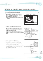
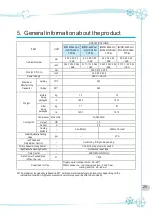
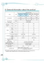
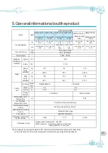
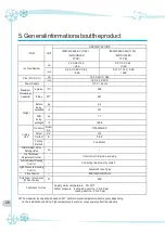
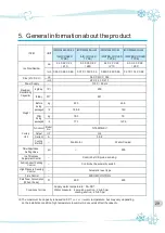


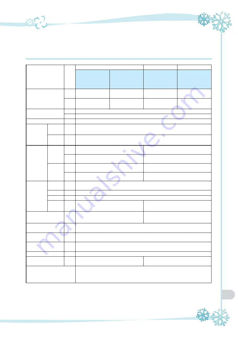
5. General information about the product
ITEM
UNIT
IM/WM-0460-AC-22
(AIR-COOLED
TYPE)
IM/WM-0460-AH-22
(AIR-COOLED
TYPE)
IM/WM-0460-WC-22
(WATER-COOLED
TYPE)
IM/WM-0460-WH-22
(WATER-COOLED
TYPE)
Ice Size/Number
mm
22 X 22 X 22
/ 210
9.5 X 29 X 22
/ 280
22 X 22 X 22
/ 210
9.5 X 29 X 22
/ 280
inch
0.86 X 0.86 X 0.86
0.37 X 1.14 X 0.86
0.86 X 0.86 X 0.86
0.37 X 1.14 X 0.86
Size (W X D X H)
mm
560 X 619 X 553
inch
22 X 24.3 X 21.7
Power Supply
-
115 V / 60 Hz
Maximum
Manufacturing
Capacitor
kg/day
10
℃
200
lb/day
50
℉
441
Weight
Before
being
packaged
kg
67.5
63.5
lb
148.8
140
After
being
packaged
kg
78.5
76
lb
173
167.6
Cooling
Unit
Compressor
Model
No.
NT6220GKV
Output
HP
3/4
Current
A
5.92
Cooling
Method
-
Fan Motor
Water Cooled
Water Adjust Valve
Setting Value
psi
-
265
Ice Thickness
Adjustment Control
-
Control by ICE probe sensing
Full Ice Amount Sensing
Control
-
Control by the proximity switch
High Pressure Sensing
Control
-
Automatic reset type
Time Control
-
MICOM CONTROL
Rate Power Consumption
(When the ice)
W
690
600
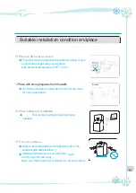
Conditions for Use
Supply water temperature : 50~90
℉
Water pressure : ice making section : 20~80 psi,
cooling section : 20~80 psi
※
The maximum ice capacity is based on 50
℉
am bient
/ water temperature, but may vary depending
on the installation condition; high temperature in summer may severely affect the capacity.
29
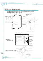
Summary of Contents for IM/WM-0460-AC
Page 34: ...MEMO 34...
Page 35: ...MEMO 35...
Page 36: ...Online Internet Service http www icetrousa com 3240288 05...


