General information
16
With these valves you can periodically test the efficiency of the level control system by performing the following operations.
Open the purge valve for a few seconds and close it again.
If the water disappears and then quickly returns to the starting point with large swings, it can be assumed that the level works well.
Whereas, if the water slowly returns or stops at a different point from the previous, it means that one of the communications is
obstructed; to ascertain which of the two and to try purging it, close the steam valve leaving the water valve open, then reopen
the purge valve: water should come from here, taking with it any muddy deposits formed in the ducts.
When the water valve is closed, the steam valve opens and steam must come out from the purge.
By closing the purge valve and leaving the two steam and water side valves open, the water must return to the starting point. If
this does not happen, clean the connecting ducts of the level indicator to the generator.
During commissioning, make sure that the vent and drain are closed. During operation the shut-off valves must be fully open.
To reduce the possible leaks, the indicators must be periodically insulated to check that the tightening torque of bolts is at least
30 Nm.
Do not proceed with maintenance without having firstly checked that:
–
The generator pressure is equal to the atmospheric pressure.
–
The indicator temperature is equal to the environment temperature.
Maintenance must be carried out when:
–
The crystal looses part of its transparency, partially opaque, signs of internal roughness due to erosion or corrosion as it in-
volves loss of geometry and reading becomes difficult.
–
Minimal leaks from the gaskets or shut-off groups are also noticed.
AUTOMATIC LEVEL REGULATOR AND SAFETY LEVEL SWITCH
The detection and control principle of the level is based on the electrical conductivity of the water.
The following conditions must be met to ensure the proper operation of the level switch:
–
Water conductivity: >250 μS/cm
–
Generator temperature: <210°C
–
Pressure: <20 bar
(See the "Operating water" paragraph).
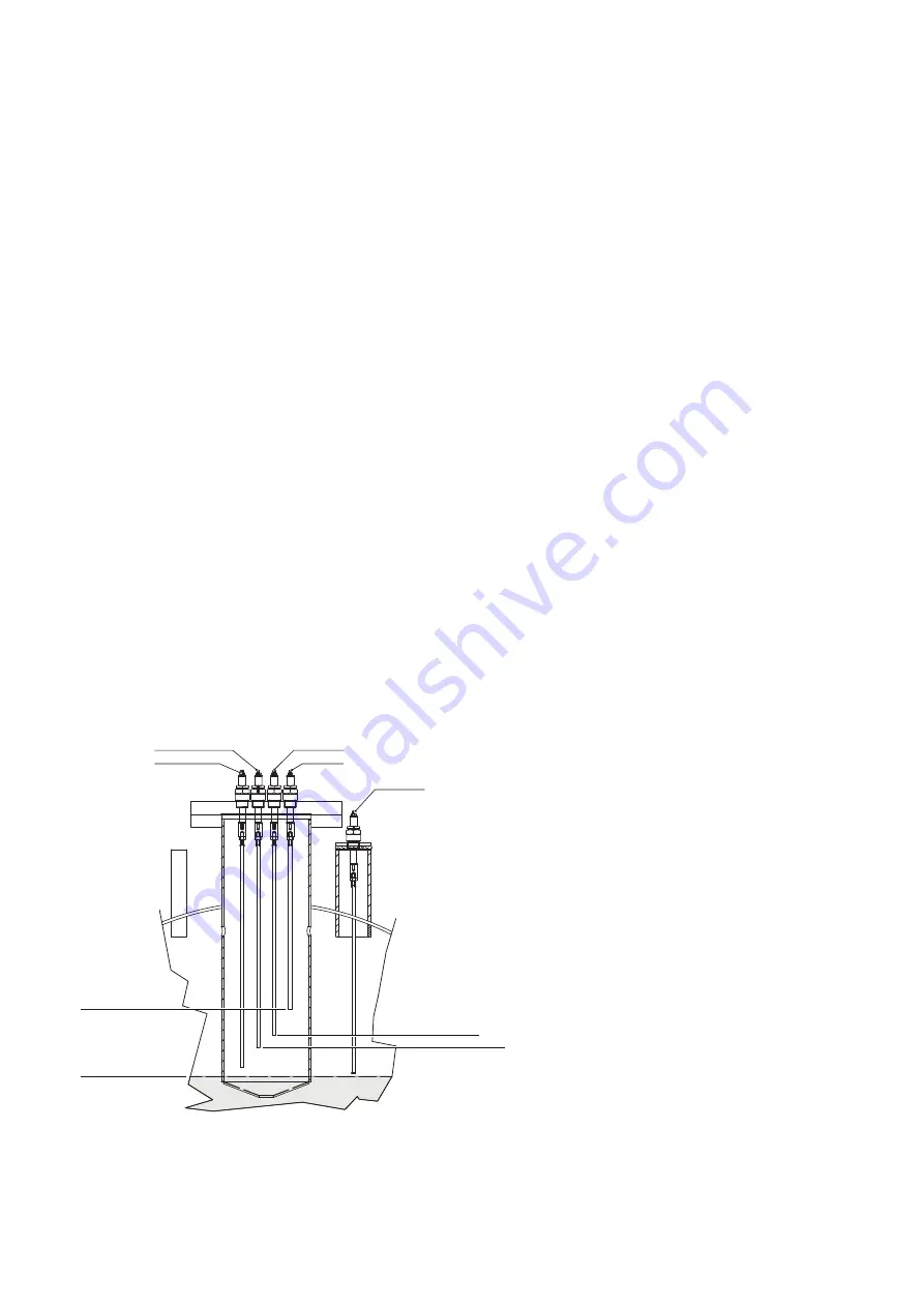
The appliance consists of a part located in the control panel (electronic relays) and probes of different length immersed in the
generator body.
The operation includes:
–
Automatic start and stop of the pump:
it is managed with two probes inserted in the generator, one longer (2) to start the
pump and one shorter (1) to stop it, connected to a single adjustment relay in the control panel
–
Burner stop for low level:
it is managed with two probes (3 and 4) of the same length, inserted in the generator and connect-
ed to two separate adjustment relays in the control panel. They generate a burner stop if the water level drops below the
minimum limit allowed.
MAX
OFF
ON
MIN
1
4
5
2
3
Probes in the generator:
1
Pump stop
2
Pump start
3
1st minimum level safety (burner lock and
alarm insertion)
4
2nd minimum level safety (burner lock and
alarm insertion)
5
Maximum level safety (optional)
N.B.: In addition to the ringing of the alarm
in the installation room, it is advisable to
add an acoustic or visual signal in a regularly
attended place.
Cooke Industries - Phone: +64 9 579 2185 Email: sales@cookeindustries.co.nz Web: www.cookeindustries.co.nz


