Installation
23
BURNER ASSEMBLY
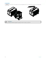
Having chosen the burner to be used, refer to the Manual supplied with it for information about:
–
the installation and fastening to the boiler
–
the connection to the fuel supply
–
the electrical connections
–
the adjustments to be made
–
maintenance
–
the necessary checks.
m
IMPORTANT
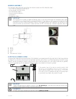
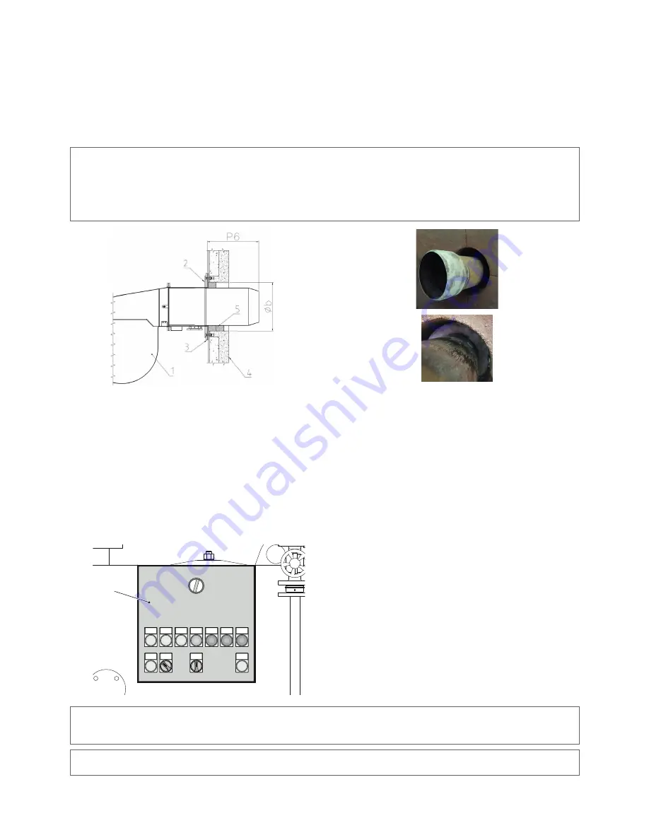
The strip of ceramic insulation supplied with the generator must be wrapped all around the mouthpiece at least once
to protect the burner flange from the irradiation of the flame. It is not necessary for the ceramic insulation to fill the
gap up to the internal surface of the door insulation. If the supplied material is not suitable for the used burner, use
other material having characteristics suitable to withstand 1000°C and dimensions suitable to completely close the
gap.
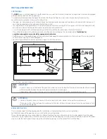
1
2
1
Burner
2
Flange
3
Gasket
4
Door
5
Thermoceramic material
ELECTRICAL CONNECTIONS
The generators are equipped with electrical panel (IP 55 protection rating) complete with all connections to the various generator
components, already made in the factory. The panel model is determined by the version of the ordered generator and the wiring
diagram, specific and detailed, is present inside the panel. The installer connections must be made by professionally qualified
personnel, in compliance with the applicable Technical Standards and the local and national Legislation.
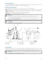
[1]
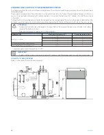
[1] For practical needs, the electric panel for models SIXEN
350÷800 vers. IT and SIXEN 350÷1350 vers. EXP is installed on
the left, while for models SIXEN 1000÷5000 vers. IT and SIXEN
1700÷5000 vers. EXP is installed on the right. The drawing shows
an example of steam boiler with panel on the right.
m
IMPORTANT
Connect the generator to an efficient earthing system.
ICI CALDAIE S.p.A.
is not liable for any damage caused by the
lack of earthing and failure to comply with the wiring diagram.
d
PROHIBITION
Do not use the water and heating system pipes for the
earthing connections
.


