47
S-DD4
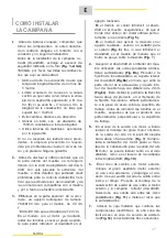
INSTALLATION DER
DUNSTABZUGSHAUBE
1.
V
o
r d
e
m
Einb
a
u des Gerii.t
s ve
rg
ew
i
sse
rn Si
e
s
i
c
h, d
ass a
ll
e
Bestandteile ni
c
ht b
esc
h
ii.
di
g
t
s
ind.
And
e
r
s
falls, bitte den V
e
rk
ii.
ufer k
o
n-
t
a
kti
e
r
e
n und d
e
n
Einbau
a
bbr
ec
hen.
Vor
ln
s
t
a
ll
a
ti
o
n d
e
r Ver
s
enkkl
a
pp
e e
ntf
e
rn
e
n
Si
e
bitt
e
d
as
in d
e
r Abbildung
geze
igt
e
Si-
c
h
e
rh
e
it
ss
tu
c
k
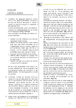
(Abb. 1-2-3-4).
Bitt
e a
ll
e
f
o
l-
g
e
nd
e
n An
we
i
s
ungen s
o
rgf
ii.
lti
g
l
ese
n
.
• Ein
Abluftrohr
ve
rw
e
nd
e
n
,
d
ass
ni
c
ht
l
ii.
n-
ge
r
a
l
s 5
M
e
t
e
r i
s
t.
•
Di
e
Z
a
hl d
e
r R
o
hrb
o
g
e
n im A
b
luftk
a
n
a
l
ve
rm
e
i
de
n
,
da jeder R
o
hrb
o
g
e
n die
L
e
i
s
-
tun
gs
f
ii.
higk
e
it um ein
lin
ea
r M
e
t
e
r
se
nkt
(z
.
B
. we
rd
e
n 2
Rohrb
o
g
e
n
9
0
°
v
erw
e
n-
d
e
t
,
mu
ss
die maximal
e
Lii.nge
de
s
Ab-
luftk
a
n
a
l
s
ni
c
ht mehr
a
l
s 3
M
e
t
e
r b
e
tr
a
-
g
e
n
)
.
•
Dr
as
ti
sc
h
e
Ri
c
htung
sii.
nd
e
run
ge
n
ve
r-
m
e
id
e
n
.
• Ein
e
R
o
hrl
e
itung
im
Dur
c
hm
esse
r
vo
n
1
5
0 mm fl.ir di
e
g
a
n
ze
Lii.n
ge
d
e
r R
a
u
c
h-
r
o
hrl
e
itung
verwe
nd
e
n.
•
M
a
t
e
ri
a
! fur R
o
hrleitung
verwe
n
de
n
, das
d
e
n N
o
rm
e
n und V
o
r
sc
hrift
e
n
e
nt
s
pri
c
ht.
B
e
i Ni
c
ht
e
inhaltung der
o
bi
ge
n An
we
i
s
un-
gen h
a
ft
e
t d
e
r
Hersteller
ni
c
ht fur
sc
hl
ec
ht
e
Abzu
gs
l
e
i
s
tungen oder
laut
es
B
e
trieb
sge
-
r
ii.
u
sc
h und
l
e
i
s
t
e
t keinerl
e
i
Ga
r
a
nti
e
.
2.
B
evo
r
de
r Ein
sc
hnitt
v
org
e
n
o
mm
e
n
w
ir
d
,
mu
ss
ub
e
rpruft
we
rd
e
n
,
d
ass s
i
c
h
im
B
ewe
-
g
ung
s
b
e
r
e
i
c
h d
e
r
Ve
r
se
nkkl
a
pp
e
k
e
in
e
Struk-
turt
e
il
e des
M
o
b
e
l
s o
d
e
r
so
n
s
ti
ge
El
e
m
e
nt
e
b
e
find
e
n
,
di
e e
in
e
korr
e
kt
e
ln
s
t
a
ll
a
ti
o
n b
e
hin-
d
e
rn
ko
nnt
e
n
.
O
be
rprl.if
e
n
,
d
ass
di
e
A
b
m
es
-
s
un
ge
n d
e
r
Ve
r
se
nkklapp
e
und d
e
r
H
e
rd
p
l
a
t-
t
e
mit d
e
n
e
n d
es
Mobel
s
tU
c
k
s ve
r
e
inb
a
r
s
ind
und di
e
ln
s
t
a
ll
a
ti
o
n also m
o
gli
c
h
i
s
t.
3.
Ein
r
ec
ht
ec
kig
es
Loch in
di
e
hinteren S
e
it
e
d
e
r K
oc
hpl
a
tt
e e
infl.igen; fur d
as 9
0
c
m-M
o
-
d
e
ll
e
in L
oc
h
vo
n 7
9
0
X
1
00 mm
,
fur d
as
1
20
c
m-
Mo
d
e
ll
e
in L
oc
h
v
on
10
90X
1
00.
Fur
d
as
M
o
d
e
ll
mit
e
ing
e
b
a
ut
e
m M
o
t
o
r mu
s
-
se
n
z
u
e
r
s
t di
e Sc
hraub
e
n
e
ntf
e
rnt und d
as
Saug
a
ggr
ega
t
bese
iti
g
t
we
rd
e
n, um d
e
n
D
ow
ndr
a
ft in d
as a
u
sge
fl.ihrt
e
Lo
c
h
e
in-
z
u
se
t
ze
n
.
Fur
das
M
ode
ll
mit Gla
ss,
d
e
n
D
ow
ndr
a
ft in
das
M
obe
l
s
tU
ck e
in
se
t
ze
n un
d
s
i
c
h
ve
r
s
i
c
h
e
rn
,
d
ass de
r
Ed
e
l
s
tahi-Ran
d
unter d
e
m Gl
ass
mit d
e
r M
o
belflii.
c
he tr
e
f-
fend ub
e
r
e
in
s
timmt
(Abb.
5)
.
Fur
das M
o
d
e
ll
lnox
au
s
Ed
e
l
s
t
a
hl mu
ss
d
e
r Gegenrahm
e
n
in
da
s a
u
sge
fuhrte
L
oc
h
e
ing
es
etzt werd
e
n;
fl.ir di
e
B
e
f
es
ti
g
ung b
e
nut
ze
n Si
e
Dichtung
s
-
m
asse
.
(Abb.
5)
D
a
n
ac
h d
e
n Do
w
ndr
a
ft
in
da
s
M
o
b
e
l
s
tu
c
k
e
in
se
t
ze
n und dar
a
uf
ac
h-
t
e
n
,
d
ass
d
e
r R
a
nd mit d
e
m G
e
g
e
nr
a
hm
e
n
tr
e
ff
e
nd ub
e
r
e
in
s
timmt
(Abb.
7)
.
4.
D
e
n D
ow
ndr
a
ft inn
e
rh
a
lb
d
es
M
o
b
e
l
s
tU
c
k
s
mitt
e
l
s de
r
bes
timmt
e
n
a
u
sges
tattet
e
n Bu
-
gel bef
es
ti
ge
n
(Abb.
Ba)
.
Die Bug
e
l
a
m unt
e
r
e
m
T
e
il d
es
D
ow
ndraft
s
befe
s
tig
e
n
(Abb.
Bb)
; z
wi
sc
hen dem unt
e
-
ren
Teil
d
es
Bu
ge
l
s
und d
e
m unteren
Teil
d
es
Mob
e
l
s
tu
c
k
s
mu
ss e
in
Ab
s
t
a
nd
v
on 2 mm
eing
e
h
a
lt
e
n
we
rd
e
n
(Abb.
Be).
Die
se
r Ab-
s
tand
e
rl
a
ubt - b
e
i B
e
f
es
tigung - d
as
G
e
r
ii.
t
na
c
h unt
e
n
z
u
z
i
e
h
e
n und d
e
n Stahi-R
a
h-
m
e
n
a
m Ar
be
it
s
ti
sc
h ri
c
htig
e
in
z
ul
e
g
e
n. B
e
-
v
or Si
e
d
as
M
o
b
e
l
s
tU
c
k mit d
e
n S
c
hraub
e
n
b
e
f
es
ti
ge
n
, ac
ht
e
n Si
e ob
d
as
G
e
rii.t au
c
h
se
nkr
ec
ht
des
Ar
be
it
s
ti
sc
h
s
h
ii.
ngt.
5.
Bei d
e
r Au
s
fuhrun
g
mit
e
ingebautem M
o
-
t
o
r mu
ss
b
e
i M
o
nt
age
d
e
r M
o
t
o
reinheit d
e
r
Luftau
s
tritt
in
die
vo
rg
ese
hene
Ri
c
htung
nach unt
e
n
o
der ob
e
n
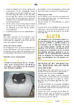
(Abb.
9)
ausgeri
c
ht
e
t
werd
e
n D
e
r M
o
tor k
a
nn
sowo
hl
a
uf d
e
r Vor-
d
e
r-
a
l
s a
u
c
h
a
uf d
e
r Ru
c
k
se
it
e
d
e
r V
e
r
se
nk-
kl
a
pp
e
in
sta
lli
e
rt
we
rd
e
n.
N
ac
h
e
rf
o
l
g
t
e
r
ln
s
t
a
ll
a
ti
o
n d
es
M
o
tors mu
ss
d
e
r K
a
n
a
l
z
ur Abfl.ihrun
g
d
e
r
Luft
m
o
nti
e
rt
we
rd
e
n
(Abb. 1
0)
.
6.
B
e
i Au
s
fuhrun
ge
n mit
ex
t
e
rn
e
m M
o
t
o
r
,
i
s
t
d
i
e
An
s
au
ge
inh
e
it
(ex
t
e
rn
e
r M
o
t
o
r
)
in ein
e
m g
e
-
eign
e
t
e
n B
e
r
e
i
c
h
a
nzubrin
ge
n und da
s
Luft-
abzug
s
r
o
hr
z
u po
s
iti
o
ni
e
r
e
n
, w
ie in
Abb. 11
darg
es
t
e
llt.
D
e
n
Luft
a
b
z
ugskanal zwi
sc
h
e
n
dem
e
xt
e
rn
e
n Motor und d
e
r Ver
s
enkkl
a
p-
pe m
o
nti
e
r
e
n. Den
Luft
a
u
s
tritt
zw
i
s
chen d
e
n
fl.inf b
es
t
e
h
e
nd
e
n M
og
li
c
hk
e
it
e
n
(Abb. 11)
aus
wii.
hl
e
n un
d
di
e
mitg
e
li
e
f
e
rt
e
Vers
c
hr
a
u-
bung
in
s
t
a
lli
e
r
e
n
.
Summary of Contents for 3D9BL
Page 2: ...2 ...
Page 6: ...6 S 004 DESCRIZIONE DELL APPARECCHIO ...
Page 16: ...S 004 16 GB DESCRIPTION OFTHE APPLIANC ...
Page 26: ...26 S 004 DESCRIPTION DE VOTRE APPAREIL ...
Page 36: ...S 004 36 DESCRIPCIÒN DELAPARATO ...
Page 46: ...46 S 004 D GERATEBESCHREIBUNG ...
Page 56: ...56 S 004 BESCHRIJVING VAN HET APPARAAT ...
Page 64: ...S 004 64 ...
Page 65: ...IMMAGINI IMAGES IMAGES AFBEELDINGEN IMAGENES BILDER S 004 1 65 ...
Page 66: ...S 004 66 ...
Page 67: ...S 004 67 ...
Page 68: ...S 004 68 C9 i i i A B c D E F ...
Page 70: ...70 ...

