
Symptom
Problem
Fan overheats, over
amps or runs very
rough
Check with the motor manufacturer to see if the motor is able
to be speed controlled by reducing the input voltage. Verify
the motor is a single phase PSC motor.
The fan cycles from
full ON to full OFF
with little or no
modulation
Check the Hard start setting in the App. Too much hard start
can drop pressure too quick causing a fan cycling effect.
Lower the hard start in the App.
Should the fan cycling persist, move the probe up several
bends into the condenser to increase the sensitivity to the
condensing temperature.
Adjust the minimum output voltage in the App while fine
tuning the probe placement on the condenser.
The fan does not
come on at all
Using an AC voltmeter, measure the voltage between the 24
VAC terminals. It should read approximately 24 volts.
Measure the line voltage between LINE 1 and LINE 2 to confirm
that line voltage is present. Check Line 1 of the ICM325A
and confirm it is connected to the same leg of power as the
common of the Run capacitor.
Remove the thermistor probe from the terminal block and
measure its resistance at ambient temperature. Compare your
reading at the appropriate temperature in Appendix B to see
if the actual resistance approximates the listed value. Next,
hold the probe in your hand and confirm that the resistance
decreases. If a pressure sensor is used, measure the DC
voltage between GND and the sensor output at BWG and
compare your reading to the expected pressure in Appendix A.
The high pressure
switch trips off
Move the probe further into the condenser where the
temperature is higher. This will produce a higher fan RPM and
will decrease the head pressure.
Fine adjust the cutout and hard start settings in the App.
GREEN
AMBER
Condition
OFF
OFF
• No voltage at L1 or L2
• No control voltage when jumper is placed
• Output is off
ON
OFF
Full Speed Operation
OFF
ON
Variable Speed Operation
OFF
2 Flashes
Shorted Sensor (Temperature or Pressure)
OFF
3 Flashes
Open Sensor (Temperature or Pressure)
TROUBLESHOOTING
LED DIAGNOSTIC INDICATORS
APPENDIX A
APPENDIX B
TEMPERATURE VS. PROBE RESISTANCE
°C
°F
Resistance (KΩ)
0°
32°
32.7
5°
41°
25.4
10°
50°
19.9
15°
59°
15.7
20°
68°
12.5
25°
77°
10.0
30°
86°
8.1
35°
95°
6.5
40°
104°
5.3
45°
113°
4.4
50°
122°
3.6
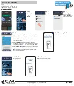
Wiring of the ICM325A to a heat pump is the same as for air conditioning with the
exception of the Motor 2 output and the reversing valve input. For a heat pump, the
ICM325A Motor 2 terminal is connected to the outdoor fan relay input power terminal
(com) on the defrost board. The condenser fan common remains connected to the
normally closed terminal of the fan relay on the defrost board. Apply the reversing
valve voltage to the HP RV input in parallel with the existing reversing valve; for cool
active reversing valves a jumper will have to be placed at the HP O RV jumper posi-
tion. NOTE: Line one of the ICM325A must share the same leg of power that is feed-
ing the common of the run capacitor.
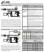
AIR CONDITIONING SYSTEM WIRING
HEAT PUMP SYSTEM WIRING
Connect the wires from the contactor (load side), run capacitor, and the condenser
fan as shown in diagram above. If control voltage is desired, ensure the jumper is
placed on the control voltage enable input and the proper voltage (24-240 VAC) is
applied to the control voltage input. Place the temperature probe at T1/P1 and 5V and
mount the probe on a U-bend in the upper third of the condenser. If two temperature
probes are needed, wire the additional temperature probe to T2/P2 & 5V. If a pressure
transducer is used, mount the transducer on the discharge line at the service fitting.
Connect the red wire to +5V, the black wire to GND and the BWG (blue/white/green)
wire to T1/P1 input. If two pressure sensors are used, connect the black and red wires
of the additional pressure sensor to the same points as previously mentioned and
connect the BWG (blue/white/green) wire to TP2/P2. NOTE: Line one of the ICM325A
must share the same leg of power that is feeding the common of the run capacitor.
Pressure (PSIG)
Voltage (VDC)
15
0.5
50
0.8
100
1.2
150
1.6
200
2.0
250
2.4
300
2.8
350
3.2
400
3.6
450
4.0
515
4.5
PRESSURE VS. VOLTAGE
MOTOR 2
ICM325A
LINE 2
LINE 1 / MOTOR 1
120 - 600 VAC
FULL SPEED
VARIABLE SPEED
CONTROL
INPUT
24-240VAC
HP RV
24-240VAC
GND
+5V
T2/P2
T1/P1
CONTROL INPUT
HP
MADE IN THE USA
SENSOR
ENABLE
Line Voltage
120-600 VAC
Place jumper to enable
the control voltage input
24-240 VAC
Control Voltage
(optional)
Temperature
Sensor
O RV
Run
Start
Common
L1
L2
T1
T2
Contactor
Run
Capacitor
To C
ompr
es
sor
Field
Ins
tal
led
W
ire
Com
Herm
Fan
Single
Phase PSC
Fan Motor
MOTOR 2
ICM325A
LINE 2
LINE 1 / MOTOR 1
120 - 600 VAC
FULL SPEED
VARIABLE SPEED
CONTROL
INPUT
24-240VAC
HP RV
24-240VAC
GND
+5V
T2/P2
T1/P1
CONTROL INPUT
HP
MADE IN THE USA
SENSOR
ENABLE
Line Voltage
120-600 VAC
Fan
Relay
Place jumper to enable
the control voltage input Place jumper to
enable a cool active
reversing valve at
the HP O RV input
24-240 VAC
reversing valve
input (heat active
default)
24-240 VAC
Control Voltage
(optional)
Temperature
Sensor
Defrost Board
COMN
Run
Start
Common
C
L1
L2
T1
T2
Contactor
Run
Capacitor
To C
ompr
es
sor
Field
Ins
tal
led
W
ire
Com
Herm
Fan
Single
Phase PSC
Fan Motor
O RV


