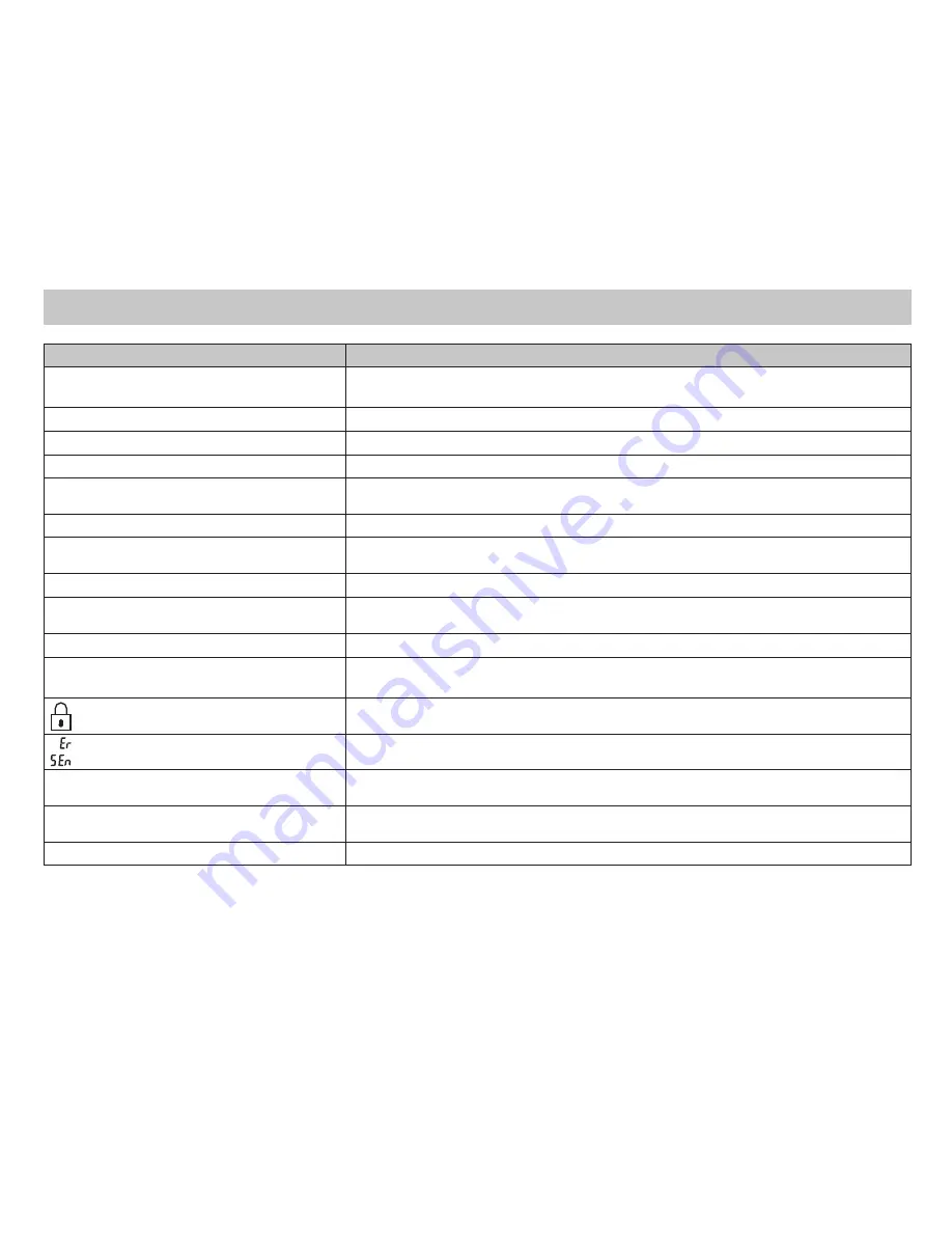
Troubleshooting
Symptom
Remedy
No display
Check for 24 VAC at thermostat; display is blank when 24 VAC is not present
Time and day of week must be reset after extended power loss
System fan does not come on properly
Verify wiring is correct, check Gas/Electric Configuration (see Setting 4, Page 12)
All thermostat buttons are inoperative
Verify 24 VAC is present; unit locks out when 24 VAC is not present
No response with first button press
First button press activates backlight only
Program schedule activates at the wrong
time
Check time (AM/PM) set on thermostat (see Setting the Time, Page 20)
Thermostat turns on and off too frequently
Adjust temperature differential (see Configuration Mode Setting 2, Page 11)
Thermostat does not follow program
Verify it is operating in program mode (PROG displays); check time (AM/PM); check
if in 2 hour program override
Fan runs continuously
Press FAN (right) button to turn fan off
Fan turns on occasionally
Program Mode: Check programmable fan setting in program schedule
(see Page 22)
Status indicator light not on during call
Turn status indicator function on (see Configuration Mode Setting 12, Page 15)
Room temperature is not correct
Calibrate thermostat (see Configuration Mode Setting 8, Page 14)
If remote sensor is used, check S1 and S2 terminal connections
displays when any button is pressed
Thermostat has the button lockout function activated (see Lockout Feature, Page
23 and Configuration Mode Setting 5, Page 13)
on display instead of room temp .
Check for a bad connection at S1 and S2 terminals, if used (see Configuration
Mode Setting 10, Page 14)
Heat or Cool not coming on
Verify wiring is correct, verify RC/RH jumper is in place (for single transformer
system)
Remote or outdoor sensor not accurate
Press SYS and Down buttons simultaneously to display remote or outdoor
temperature . Verify connections at S1 and S2 terminals .
Problem not listed above
Press Reset button once*
* Reset Button Function
Time and day are reset, configuration and program settings are unchanged .
Summary of Contents for SC 5011
Page 7: ... Hardwired 3 Wire Single Transformer Hardwired 4 Wire Single Transformer Wiring Diagrams ...
Page 9: ... Hardwired Cool or Heat Active Reversing Valve ...
Page 10: ... Hardwired 4 Wire Single Transformer ...
Page 30: ...This page left blank intentionally ...


