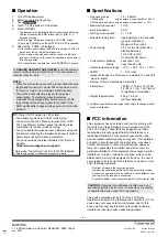
–
3
–
–
2
–
NOTE:
• Disconnect the control cable from the antenna
tuner when the tuner will not be used for some time.
Otherwise, the installed alkaline batteries will become
exhausted.
• When the batteries are almost exhausted, the antenna
tuner is automatically turned OFF. Replace all batteries
with new alkaline batteries.
■
About power supply
D
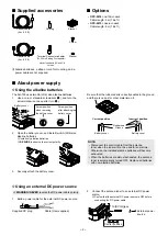
Using the alkaline batteries
The AH-705 uses two AA (LR6) size alkaline batteries.
1.
Use a coin or standard screwdriver (
1
), and turn the
screw clockwise one quarter turn (
2
).
2.
Open the battery cover, and Install two AA (LR6) size
alkaline batteries.
L
Install only alkaline batteries.
L
BE SURE
to observe the correct polarity.
3.
Securely attach the battery cover.
Battery cover
Screw position
when removing
the battery cover.
Screw position
after attaching the
battery cover.
D
Using an external DC power source
R
WARNING! NEVER
reverse the DC power cable polarity.
1.
Build a power cable for the external DC power source.
2.
Connect the antenna tuner to an external DC power
source.
L
Confirm that the external DC power source is OFF before
connecting the DC power cable.
Supplied DC plug
Cable (User supplied)
■
Connection
■
Installation
Install the antenna tuner on a pole, as shown below.
1.
Attach the supplied bracket to the back of the antenna
tuner, by using a coin or standard screwdriver.
You can hang the antenna
tuner, by threading a piece
of cord through the bracket.
Installation example:
2.
Thread the strap through
the bracket slots.
Correct position
Incorrect position
Groove
Rubber seal
Battery cover
+
_
_
Center positive
To [DC IN] jack
GND
AH-705
Control cable
( Supplied cable: 2 m, 6.5 ft
Optional cable: 5 m, 16.4 ft)
To [TUNER] jack
To [ANT] connector
To [CTRL] jack
GND
IC-705
To antenna
connector
Supplied Terminal
Connector adapter
You can also connect
a banana plug.
Long wire antenna
Strap (User supplied)
Supplied screw
Supplied washer
Supplied bracket
Battery cover
NOTE:
• Keep the antenna tuner as far away from the transceiver
as possible.
•
DO NOT
expose the tuner to rain, snow, or any liquids,
when the jack covers are detached. Dust-protection and
splash resistance cannot be guaranteed.
• Using the tuner with a Loop antenna that is not suitable
for the operating frequency cannot be guaranteed.
NOTE:
The antenna tuner must have an adequate ground connection. Otherwise, the overall efficiency of the transceiver and
antenna tuner installation will be reduced. Interference, RF feedback, and electrical shocks from other equipment could also
occur.
For best results, connect a heavy gauge wire or strap to a long ground rod. Make the distance between the [GND] terminal
and ground as short as possible.
• A long wire connected to the [GND] terminal can be used as a counterpoise.
GND
External power
source
3.
Mount the antenna tuner on a pole.
Be sure that the rubber seal is correctly seated in the groove,
and there is no dust or other material on it.
22 mm (0.9 inch)
2 mm
(0.1 inch)
5.3 mm
(0.2 inch)
Slot dimensions
HF/6 m antenna
Antenna element
Coaxial cable
■
Options
•
OPC-2474
control cable
Cable length: 5 m (16.4 ft)
•
OPC-2475
coaxial cable
Cable length: 5 m (16.4 ft)
■
Supplied accessories
Coaxial cable
(2 m, 6.5 ft)
Control cable
(2 m, 6.5 ft)
DC plug
L
Alkaline batteries, a strap or cord for mounting, and a
power cable are not supplied.
Terminal Connector adapter
(PL-259 to Binding Post adapter)
* Not included with EU and UK
version.
Washer
Bracket
Screw
Coaxial cable
( Supplied cable: 2 m, 6.5 ft
Optional cable: 5 m, 16.4 ft)
GND


