4 - 4
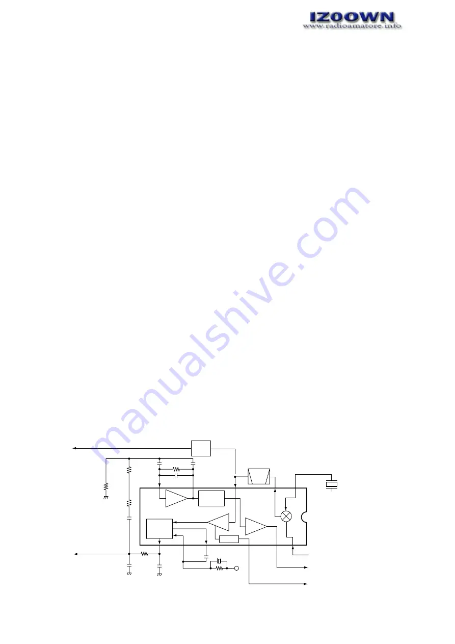
The 46.05 MHz 1st IF signal from the IF amplifier (Q1041) is
applied to the 2nd mixer section of the FM IF IC (IC1004, pin
16), and is mixed with the 2nd LO signal (45.595 MHz) to be
converted to a 455 kHz 2nd IF signal.
The 2nd IF signal is applied to the each demodulator circuits
by AM or FM mode.
• FM MODE
The 2nd IF signal is output from the FM IF IC (IC1004, pin 3)
and passes through the ceramic bandpass filter (FI1002).
The filtered signal is fed back to the IC, and amplified at the
limiter amplifier section (pin 5), then demodulated into AF sig-
nals at the quadrature detector section (pins 10, 11). The
detected AF signals are output from pin 9 and are applied to
the AF circuit via the AM/FM selector circuit (IC2016, pins 7,
1).
• AM MODE
The 2nd IF signal is output from the FM IF IC (IC1001, pin 3)
and passes through the ceramic bandpass filter (FI1002).
The filtered signal is applied to the AM detector circuit
(Q1025) to convert into AF signals, and then amplified at the
Q1022 (pins 5, 1). The amplified AF signals are applied to the
AF circuit via the AM/FM selector circuit (IC2016, pins 6, 1).
4-1-10 AF AMPLIFIER CIRCUIT FOR RIGHT SIDE
DISPLAY (MAIN UNIT)
The AF amplifier circuit amplifies the demodulated AF signals
to drive a speaker.
The AF signals pass through the AF mute switch (Q1011),
and are then applied to the electric volume control circuit
(IC2011, pin 8) as “UAFO” signal after being passed through
the low-pass filter (Q1008). The level controlled AF signals
are output from pin 7, and are then applied to the AF power
amplifier (IC2012, pin 5) via the “VOUT2” signal. The power
amplified AF signals are applied to the internal speaker (SP1)
via the [EXT SP] jack (J2004).
When no plug is connected to the jack, the signals are fed
back to the UHF audio input (IC2012, pin 2) and combined
with the UHF audio. The mixed audio is applied to the other
external speaker jack (J2005) and then to the internal speak-
er.
The electronic volume control circuit controls AF gain, there-
fore, the AF output level is according to the [VOL] setting and
also the squelch conditions.
4-1-11 NOISE SQUELCH CIRCUIT FOR RIGHT SIDE
DISPLAY (MAIN UNIT)
• NOISE SQUELCH
A noise squelch circuit cuts out AF signals when no RF sig-
nal is received. By detecting noise components in the AF sig-
nal, the squelch circuit switches the AF mute switch.
A portion of the AF signals from the FM IF IC (IC1004, pin 9)
are applied to the active filter section (IC1004, pin 8). The
active filter section amplifies and filters noise components.
The filtered signals are applied to the noise detector section
and output from the IC1004 (pin 14) as the “R_SQL” signal.
The “R_SQL” signal from IC1004 (pin 14) is applied to the
CPU (IC2013, pin 38). The CPU analyzes the noise condition
and outputs the “R_DET_MUTE” signal (pin 58) to the AF
mute switch (Q1011).
• TONE SQUELCH
The tone squelch circuit detects AF signals and opens the
squelch only when receiving a signal containing a matching
subaudible tone (CTCSS). When tone squelch is in use, and
a signal with a mismatched or no subaudible tone is
received, the tone squelch circuit mutes the AF signals even
when noise squelch is open.
A portion of the AF signals from the FM IF IC (IC1004, pin 9)
passes through the low-pass filter (Q1004) to remove AF
(voice) signals. The filtered signal is applied to the CTCSS
decoder which is inside the CPU (IC2013, pin 39) via the
“R_DTCS_IN” line to control the AF mute switch (Q1011).
16
Limiter
amp.
2nd IF filter
455 kHz
X1002
45.595 MHz
RSSI
IC1004 TA31136F
14
1st IF (46.05 MHz)
from Q1041
"R_RSSI" signal to the CPU
(IC2013, pin 32
11
10
9
8
7
5
3
2
Active
filter
FI1002
Noise
detector
FM
detector
Noise
comp.
"R_SQL" signal to the CPU
(IC2013, pin 38)
12
R1187
C1148
C1145
R1174
C1131
C1035
C1034
Q1022,
Q1025
C1044
AM
DET.
C1122
R1164
R1168
R1175
R1179
R_R5
X1002
FM AF signal
to AM/FM selector
AM AF signal
to AM/FM selector
Mixer
2nd
• 2ND IF AND DEMODULATOR CIRCUIT FOR RIGHT SIDE DISPLAY


