

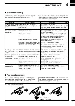


■
Receiving and transmitting
D
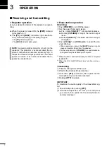
Repeater operation
Ask your dealer for details of the repeater’s program-
ming.
➥
When the power is turned ON, the
[PWR]
indicator
lights green. (p. 1)
➥
The
[TX]
and
[BUSY]
indicators light simultane-
ously while transmitting or receiving a signal.
• The
[TX]
indicator lights red.
• The
[BUSY]
indicator lights green.
NOTE:
A power amplifier protector is built into the
repeater. The protector is activated when the re-
peater’s temperature becomes extremely high, to
reduce the transmit output power level. The output
power will return to its normal level when the re-
peater has cooled down.
D
Base station operation
Receiving
q
Push
[POWER]
to turn ON the power.
w
Set the squelch and audio levels.
➥
First, rotate
[SELECT]
*
1
fully counterclockwise.
➥
Rotate
[VOLUME]
to adjust the audio output
level.
➥
Rotate
[SELECT]
*
1
clockwise until the noise just
disappears.
e
Push
[CH Up]
*
2
or
[CH Down]
*
2
to select the de-
sired channel.
• When receiving a signal, the
[BUSY]
indicator lights
green and audio is heard from the speaker.
• Further adjustment of
[VOLUME]
to a comfortable lis-
tening level may be necessary at this point.
*
1
When the [SQL Level Up/Down] key function is assigned
to [SELECT].
*
2
When the [CH Up]/[CH Down] key functions are as-
signed.
Transmitting
q
Take the microphone off the hook.
w
Wait for the channel to become clear.
e
Hold down
[PTT]
to transmit, then speak into the
microphone at your normal voice level.
r
Release
[PTT]
to receive.
IMPORTANT:
To maximize the audio quality of the transmitted sig-
nal:
(1) Pause briefly after pushing
[PTT]
.
(2) Hold the microphone 5 to 10 cm (2 to 4 inch) from
your mouth, then speak into the microphone at a
normal voice level.
3
7
OPERATION
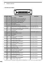
Summary of Contents for iC-FR5000
Page 1: ...INSTRUCTION MANUAL VHF dPMR REPEATER iFR5000 iFR6000 UHF dPMR REPEATER...
Page 13: ...MEMO...
Page 14: ...MEMO...
Page 15: ...MEMO...