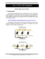
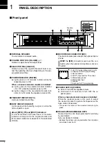
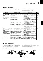
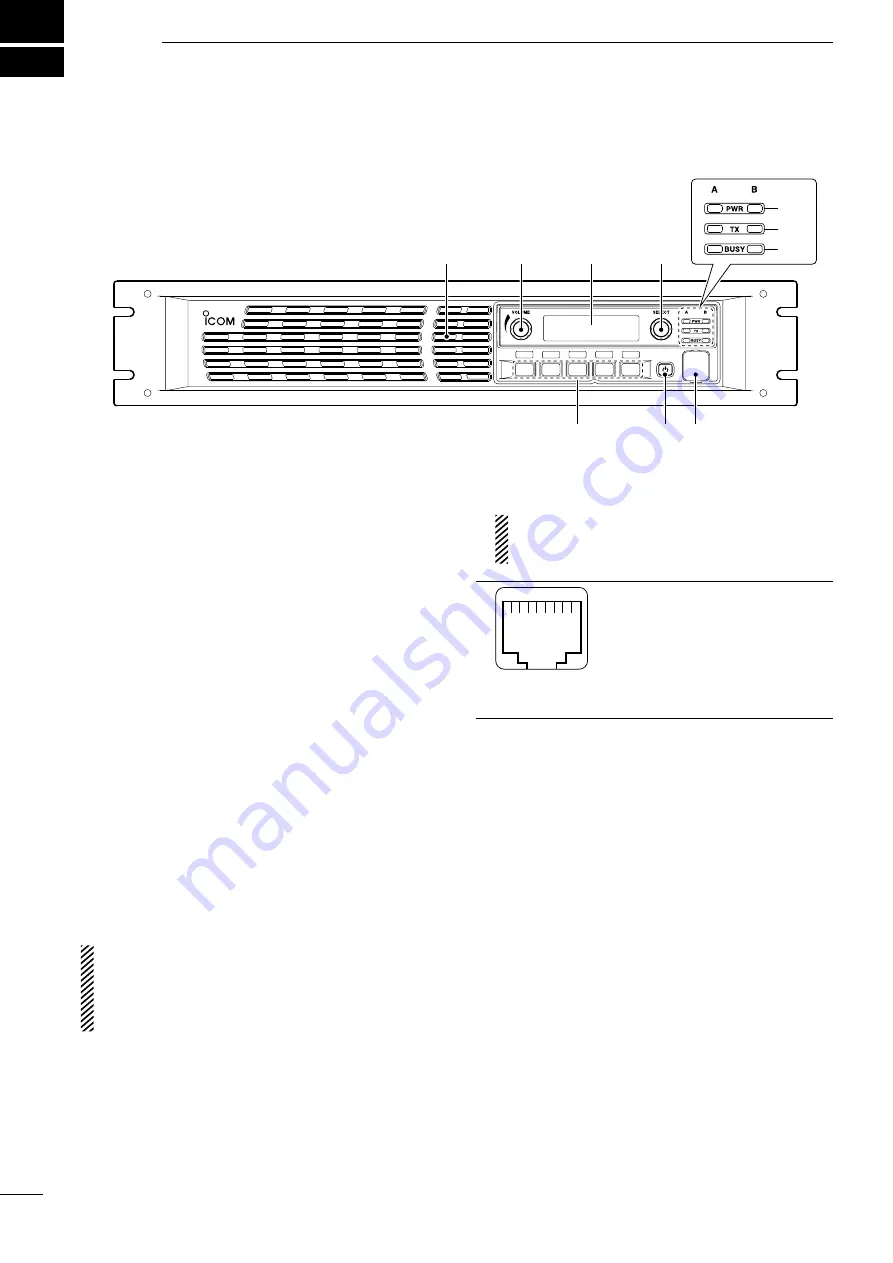
background image

1

PANEL DESCRIPTION

2001 NEW

1

q

 INTERNAL SPEAKER

  You can listen to received audio.

w

 VOLUME CONTROL [VOLUME]

 (p. 7)

  Rotate to adjust the audio output level.

e

 SELECTOR DIAL [SELECT]

   Rotate to adjust the squelch threshold level or se-

lect the operating channel. (Depending on the pre-
programmed setting.)

r

 POWER INDICATOR [POWER]


  Lights green on ‘A’ module’s indicator while the 

repeater power is ON.

  When a channel extension module is installed:


  Lights green on the selected module indicator 

(‘A’ or ‘B’) while the repeater power is ON.


  Lights orange on the un-selected module indi-

cator (‘A’ or ‘B’) while the repeater power is ON.

t

 TRANSMIT INDICATOR [TX]

   Lights red while transmitting.

y

 BUSY INDICATOR [BUSY]

   Lights green while receiving a signal or while the 

noise squelch is open.

About [PWR], [TX] and [BUSY] indicators:

‘A’ and ‘B’ modules both have these. ‘A’ module’s 
indicators correspond to the original module, and 
‘B’ module’s indicators correspond to the extended 
module.

u

 MICROPHONE CONNECTOR [MIC]

   This 8-pin modular jack accepts the optional micro-

phone.


 KEEP

 the 

[MIC]

 connector cover over the con-

nector when the optional microphone is not con-
nected.

i

q

q

 +8 V DC output (Maximum 15 mA) 

w

 Output port for PC programming 
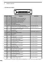
e

 No Connection 

r

 M PTT (Input port for TX control) 

t

 Microphone ground 

y

 Microphone input 

u

 Ground 

i

 Input port for PC programming

i

 POWER SWITCH [POWER]


  Push to turn ON the repeater power.


  Hold down for 3 seconds to turn OFF the re-

peater power.

  When a channel extension module is installed:

   While the repeater power is ON, push to select 

the desired module to operate the repeater as the 
base station transceiver.

  •  The power indicator of the selected module lights 

green.

o

 DEALER-PROGRAMMABLE KEYS

   Desired functions can be programmed for each key 

by your dealer. 

   Ask your dealer for details.

  •  Because these keys are programmable, their functions 

are unique to each unit.

P

0

P

1

P

2

P

3

P

4

q

w

e

i

u

o

Function
display

y

t

r


Front panel

Summary of Contents for iC-FR5000

Page 1: ...INSTRUCTION MANUAL VHF dPMR REPEATER iFR5000 iFR6000 UHF dPMR REPEATER...

Page 2: ...174 MHz 400 to 470 MHz PC programmable 19 inch rack mount Optional Voice Scrambler Unit UT 109R UT 110R for using the repeater as the base sta tion transceiver IMPORTANT READ THIS INSTRUCTION MANUAL...

Page 3: ...nlight DO NOT put anything on top of the repeater This will obstruct heat dissipation BE CAREFUL The heatsink will become hot when operating the repeater continuously for long periods BE CAREFUL If a...

Page 4: ...e original module and B module s indicators correspond to the extended module u MICROPHONE CONNECTOR MIC This 8 pin modular jack accepts the optional micro phone KEEP the MIC connector cover over the...

Page 5: ...o transmit signals q w e t r An optional channel extention module can be installed Ask your dealer for details q SIGNAL STRENGTH ICON Indicates the relative signal strength level w LOW POWER ICON Appe...

Page 6: ...DC output Customize A D input Not used No connection Ground A desired function can be assigned Default Null A desired function can be assigned Default P0 Monitor Output A desired function can be assi...

Page 7: ...for desired band Of course the transmission line should be a coaxial cable CAUTION Protect repeater from lightning by using a lightning arrestor NOTE There are many publications that describe proper a...

Page 8: ...r M PTT Input port for TX control t Microphone ground y Microphone input u Ground i Input port for PC programming Rear panel connection ACC CONNECTOR p 3 Used for external equipment control RX ANT p 4...

Page 9: ...ower cable Mounting the repeater D Using the supplied handles The handles are convenient for mounting the repeater into a 19 inch rack The handles can be installed on the repeater s front panel q Atta...

Page 10: ...ully counterclockwise Rotate VOLUME to adjust the audio output level Rotate SELECT 1 clockwise until the noise just disappears e Push CH Up 2 or CH Down 2 to select the de sired channel When receiving...

Page 11: ...duplex Turn ON the power supply Re connect the DC power cable correctly Check the cause then replace the fuse with a spare one Rotate VOLUME clockwise to obtain a suitable listening level While in ba...

Page 12: ...ice scrambler unit Rolling type maximum 1020 codes The scrambler systems of the UT 109R and UT 110R are not compatible with each other Approved Icom optional equipment is designed for op timal perform...

Page 13: ...MEMO...

Page 14: ...MEMO...

Page 15: ...MEMO...

Page 16: ...1 1 32 Kamiminami Hirano ku Osaka 547 0003 Japan A 6980H 1EX 0a Printed in Japan 2011 2014 Icom Inc Printed on recycle paper with soy ink...

Reviews: