background image

iii

RADIO OPERATOR WARNING

Your Icom radio generates RF electromagnetic energy dur-
ing transmit mode. This radio is designed for and classified as  
“General Population Use” in an uncontrolled environment.
This radio has been evaluated for compliance at the distance 
of 2.5 cm (1 inch) with the FCC and IC RF exposure limits for 
“General Population Use.” In addition, your Icom radio complies 
with the following Standards and Guidelines with regard to RF 
energy and electromagnetic energy levels and evaluation of 
such levels for exposure to humans:

  •  FCC OET Bulletin 65 Edition 01-01 Supplement C, Evaluating Compli

-

ance with FCC Guidelines for Human Exposure to Radio Frequency 
Electromagnetic Fields.

  •  American National Standards Institute (C95.1-1992), IEEE Standard 

for Safety Levels with Respect to Human Exposure to Radio Frequency 

Electromagnetic Fields, 3 kHz to 300 GHz.

  •  American National Standards Institute (C95.3-1992), IEEE Recom

-

mended Practice for the Measurement of Potentially Hazardous Electro-
magnetic Fields– RF and Microwave.

  •  The following accessories are authorized for use with this product. Use of 

accessories other than those specified may result in RF exposure levels 
exceeding the FCC and IC 

requirements for wireless RF exposure.; Belt 

Clip (MB-133).

To ensure that your expose to RF electromagnetic energy 
is within the FCC and IC allowable limits for general popu-
lation use, always adhere to the following guidelines:

  •  

DO NOT operate the radio without a proper antenna attached, as this 
may damaged the radio and may also cause you to exceed FCC and 
IC RF exposure limits. A proper antenna is the antenna supplied with 
this radio by the manufacturer or antenna specifically authorized by the 
manufacturer for use with this radio.

  •  

DO NOT

 transmit for more than 50% of total radio use time (“50% duty 

cycle”). Transmitting more than 50% of the time can cause FCC 

and IC 

RF exposure compliance requirements to be exceeded. The radio is 
transmitting when the “transmit indicator” appears on the LCD. You can 
cause the radio to transmit by pressing the “PTT” switch.

  •  

ALWAYS keep the antenna at least 2.5 cm (1 inch) away from the body 
when transmitting and only use the Icom belt clip which is listed on page 

30 when attaching the radio to your belt, etc., to ensure FCC 

and IC RF 

exposure compliance requirements are not exceeded. To provide the re-
cipients of your transmission the best sound quality, hold the antenna at 
least 5 cm (2 inches) from your mouth, and slightly off to one side.

The information listed above provides the user with the information needed 
to make him or her aware of RF exposure, and what to do to assure that this 
radio operates with the FCC and IC RF exposure limits of this radio.

Electromagnetic Interference/Compatibility

During transmissions, your Icom radio generates RF energy that can possibly 
cause interference with other devices or systems. To avoid such interference, 
turn off the radio in areas where signs are posted to do so. 

DO NOT operate 

the transmitter in areas that are sensitive to electromagnetic radiation such as 
hospitals, aircraft, and blasting sites.

Summary of Contents for IC-M25

Page 1: ...TION MANUAL iM25EURO iM25 VHF MARINE TRANSCEIVER This device complies with Part 15 of the FCC Rules Operation is subject to the condition that this device does not cause harmful interference IC M25 IC M25EURO ...

Page 2: ...injury fire hazard or electric shock may occur CAUTION Equipment damage may occur NOTE If disregarded only inconvenience No risk of personal injury fire or electric shock FEATURES Floats on water The transceiver floats in fresh or salt water even when the supplied accessories are attached It may sink when a third party accessory is attached Floats and flashes An LED sends out intermittent light fr...

Page 3: ...e of the distress and assistance re quired 6 Any other information which might facilitate the rescue CLEAN THE TRANSCEIVER THOROUGHLY WITH FRESH WATER after exposure to saltwater and dry it before operating Otherwise the transceiver s keys switches and controllers may become unusable due to salt crystallization NOTE DO NOT wash the transceiver in water if there is any reason to suspect the waterpr...

Page 4: ... the radio without a proper antenna attached as this may damaged the radio and may also cause you to exceed FCC and IC RF exposure limits A proper antenna is the antenna supplied with this radio by the manufacturer or antenna specifically authorized by the manufacturer for use with this radio DO NOT transmit for more than 50 of total radio use time 50 duty cycle Transmitting more than 50 of the ti...

Page 5: ...i risque d endommager la radio et causer une exposition supérieure aux limites établies par la FCC et d IC L antenne appropriée est celle qui est fournie avec cette radio par le fabricant ou une antenne spécialement autorisée par le fabricant pour être utilisée avec cette radio NE PAS émettre pendant plus de 50 du temps total d utilisation de l appareil 50 du facteur d utilisation Émettre pendant ...

Page 6: ...t actually intending to transmit DO NOT modify the radio The radio warranty does not cover any problems caused by unauthorized modification DO NOT operate the radio near unshielded electrical blasting caps or in an explosive atmosphere DO NOT use or place the radio in direct sunlight or in areas with following temperatures range For the USA and EXP versions Below 20 C 4 F or above 60 C 140 F For t...

Page 7: ...ting the squelch level 11 Monitor function 11 Toggling the transmit power 11 Volume Loud function 12 Volume Mute function 12 Lock function 12 AquaQuake Water Draining function 13 Setting the Call channel 13 5 SCAN OPERATION All except the HOL version 14 15 Scan types 14 Setting Favorite channels 15 Starting a scan 15 6 DUALWATCH AND TRI WATCH 16 Description 16 Operation 16 7 SET MODE 17 21 Set mod...

Page 8: ...y to operate this device under FCC regulations FCC INFORMATION COUNTRY CODE LIST ISO 3166 1 Country Codes Country Codes 1 2 3 4 5 6 7 8 9 10 11 12 13 14 15 16 17 Austria Belgium Bulgaria Croatia Czech Republic Cyprus Denmark Estonia Finland France Germany Greece Hungary Iceland Ireland Italy Latvia AT BE BG HR CZ CY DK EE FI FR DE GR HU IS IE IT LV 18 19 20 21 22 23 24 25 26 27 28 29 30 31 32 33 L...

Page 9: ...LICENSE A Restricted Radiotelephone Operator Permit is the license most often held by small vessel radio operators when a radio is not required for safety purposes If required the Restricted Radiotelephone Operator Permit must be posted or kept with the operator If required only a licensed radio operator may operate a transceiver However non licensed individuals may talk over a transceiver if a li...

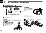
Page 10: ...Handstrap Pass the handstrap through the loop on the back side of the transceiver to make it easy to carry Belt clip Attach or detach the belt clip Handstrap Belt clip Antenna 5 V 1 A Power adapter Not supplied or the shape is different depending on the transceiver version To attach the belt clip To detach the belt clip Be careful Don t break your fingernail q Belt clip w Lift the tab up q and sli...

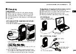
Page 11: ...pproximately 3 hours e e The charging time differs depending on the battery condition FL is displayed when the battery has been fully charged IMPORTANT Read Section 8 Pages 22 to 24 before charging Before using the transceiver for the first time fully charge the battery for optimum life and operation Turn OFF the power while charging to avoid damage to the battery Charging Supplied power adapter C...

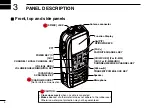
Page 12: ...P MIC JACK Antenna connector CH WX U I C For IC M25 CH For IC M25EURO CHANNEL WEATHER CHANNEL KEY FAV FAVORITE CHANNEL KEY Microphone CAUTION Close up securely when no cable is conencted Make sure dust or other material does not adhere to the rubber seal Otherwise waterproof protection may not be guaranteed CHARGE SOCKET Hi Lo TRANSMIT POWER LOCK KEY POWER KEY Not for data communication ...

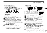
Page 13: ...en closing the socket cover Stand the transceiver up straight Otherwise any water that is on the socket cover will get into the transceiver UP DOWN KEYS Y or Z Push to select the operating channel Push to change the volume squelch level while adjusting In the Set mode push to select an item option FAVORITE CHANNEL KEY FAV Page 15 Push to sequentially select a Favorite channels while ignoring norma...

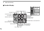
Page 14: ...ADOUT BATTERY ICON TRANSMIT ICON LOW POWER ICON FAVORITE CHANNEL ICON CHANNEL GROUP ICONS KEY LOCK ICON WEATHER ALERT ICON WEATHER CHANNEL ICON CALL CHANNEL ICON SUB CHANNEL VOL SQL LEVEL SET MODE ITEM READOUT VOLUME SQUELCH LEVEL INDICATOR DUPLEX ICON TRI WATCH ICON DUALWATCH ICON SCAN ICON Blinks while adjusting SQL for Squelch level VOL for Volume level ...

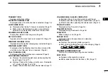
Page 15: ...plays the volume squelch level while adjusting the level Pages 10 and 11 Displays Channel 16 during a priority scan Dualwatch or Tri watch Pages 14 and 16 Displays the Set mode item while in the Set mode Page 17 VOLUME SQUELCH LEVEL INDICATOR Number of bars shows the volume squelch level SQL blinks when adjusting the squelch level Page 11 VOL blinks when adjusting the volume level Page 10 TRI WATC...

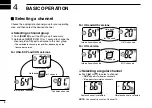
Page 16: ...l groups differ depending on the transceiver version For USA EXP and CHN versions For UK and AUS versions For HOL version Selecting a regular channel Push Y or Z to select a channel DUP appears for duplex channels A appears for simplex channels NOTE You cannot transmit on Channel 70 U S A channels International channels Canadian channels Hold down for 1 second International channels Hold down for ...

Page 17: ...t your most often used channel See page 13 Weather channels For USA EXP CHN and AUS versions The transceiver has 10 weather channels These are used for monitoring the broadcasts from the National Oceanic and Atmospheric Administration NOAA Push q q CH WX once or twice to select the Weather channel group WX appears when a weather channel is selected Push w w Y or Z to select a weather channel About...

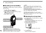
Page 18: ...o signal is received for 5 seconds When the temperature is extremely low the battery protection function automatically sets transceiver power to Low and disables High power selection For USA and AUS versions To prevent prolonged transmission a time out timer cuts OFF after 5 minutes of continuous transmission Adjusting the volume level You can adjust the volume level while the VOL icon is blinking...

Page 19: ...ction The Monitor function momentary cancels the squelch function You can check for weak signals Hold down MONI VOL SQL for 1 second blinks If there is a weak signal you can hear the signal and noise Release MONI VOL SQL to turn OFF this function NOTE This function has options See page 19 for more Toggling the transmit power If you receive no response to your call your transmitted signal might not...

Page 20: ...lume level is set to the minimum level OFF Push VOL SQL and Z again to turn OFF the function Lock function This function electronically locks most keys to prevent accidental changing of the channel and function access Hold down Hi Lo for 1 second to turn the function ON or OFF NOTE PTT VOL SQL MONI VOL SQL and Hi Lo are not locked Y and Z are not locked when adjusting the volume or squelch or when...

Page 21: ... changes to 2 short beeps to enter the Call channel setting mode The channel number starts blinking Push r r Y or Z to select the new Call channel Push t t 16 C to set the displayed channel 2 short beeps sound The channel number stops blinking AquaQuake Water Draining function Water in the speaker grill may muffle the sound coming from the speaker The AquaQuake Water Draining function removes wate...

Page 22: ...l is received On Channel 16 The scan pauses until the signal on Channel 16 disappears On a channel other than Channel 16 The scan switches to Dualwatch until the signal disappears NORMAL SCAN A normal scan sequentially searches through all Favorite channels However Channel 16 is not checked unless it is set as a Favorite channel For USA EXP CHN and AUS versions When the Weather Alert function is a...

Page 23: ...All Favorite channels in the selected channel group are cleared When no channel is set as Favorite channel Holding down FAV turn ON the power sets all channels as Favorite channels Starting a scan Hold down q q U I C CH WX for 1 second to change the channel group Repeat to advance to the desired group When the Weather Alert function is in use select a desired weather channel by pushing CH WX and Y...

Page 24: ...i watch push DUAL SCAN again When a signal is received On Channel 16 Dualwatch Tri watch pauses on Channel 16 until the signal disappears On the Call channel Tri watch switches to Dualwatch until the signal on the Call channel disappears Dualwatch Tri watch Ch 88 Ch 16 Ch 88 Ch 16 Ch 9 Monitors Channel 16 while receiving on another channel Monitors Channel 16 and the Call channel while receiving o...

Page 25: ...elect an item option Push t t 16 C to exit the Set mode 17 7 SET MODE 1 2 3 4 5 6 7 8 9 10 11 12 13 14 15 16 SET MODE ITEMS The chart shows the default settings Default values differ depending on the transceiver version Auto scan Starting item Beep tone Scan resume timer Dual Tri watch Automatic backlighting Power save Float Alert Automatic AquaQuake LCD contrast Monitor key action Priority scan W...

Page 26: ...version The transceiver has 2 scan types Normal and Priority OFF A normal scan which searches all Favorite channels in the selected channel group ON A priority scan which sequentially searches all Favorite channels while monitoring Channel 16 Scan resume timer S_ti Not available in the HOL version Select a scan resume timer option OFF When a signal is received the scan pauses on the channel until ...

Page 27: ...momentary activates the Monitor function Select a key action option Pu PUSH The Monitor function is activated while holding down MONI VOL SQL for more than 1 second The squelch function is canceled while holding down the key Ho HOLD The Monitor function is activated by holding down MONI VOL SQL for more than 1 second The squelch function is canceled until MONI VOL SQL is pushed again 19 7 SET MODE...

Page 28: ...ontrast setting Lcdc Set the LCD contrast level to High or Low The LCD contrast level has little effect during indoor use Power Save function P_SA The Power Save function reduces current drain by periodically turning OFF the receiver circuit OFF The function is turned OFF ON When no signal is received and no operation is performed for 5 seconds the receiver circuit is periodically turned OFF Backl...

Page 29: ... is retrieved from the water CAUTION The alarm sounds loudly Automatic AquaQuake function AquA This function automatically activates the AquaQuake Water Draining function when the transceiver is retrieved from the water OFF The function is OFF 2 5 10 The AquaQuake Water Draining function is automatically activated after stopping the floating alarm sound A low vibration tone sounds for the specifie...

Page 30: ...tery life Battery caution R DANGER DO NOT expose the battery to rain snow seawater or any other liquids Do not charge or use a wet battery If the battery gets wet be sure to wipe it dry before using The battery by itself is not waterproof R DANGER NEVER incinerate the transceiver since internal battery gas may cause them to rupture or may cause an explosion R DANGER NEVER solder the battery termin...

Page 31: ... C to 50 C 4 F to 122 F within a month 20 C to 35 C 4 F to 95 F within three months 20 C to 25 C 4 F to 77 F within a year Charging caution R DANGER NEVER charge the battery in areas with extremely high temperatures such as near fires or stoves inside a sun heated car or in direct sunlight In such environments the safety protection circuit in the battery will activate causing the battery to stop c...

Page 32: ... discharging cycles is between 300 and 500 depending on the type of operation Even when the battery appears to be fully charged the operating time of the transceiver may become short when Approximately five years have passed since the battery was manufactured The battery has been repeatedly charged BE SURE to replace the battery with a new one approximately five years after manufacturing even if i...

Page 33: ...peaker mic connector into the SP MIC connector and securely screw it as shown below Be careful not to cross thread the connection IMPORTANT KEEP the transceiver s SP MIC cap attached when the speaker microphone is not used If the cover is not attached water will get into the transceiver Moreover the terminals pins will become rusty or the transceiver will function abnormally if the connector gets ...

Page 34: ...to select a number Pushing VOL SQL selects the previous digit After the 10th digit has been input t t push Hi Lo to store the code The code number stops blinking Push 16 C to return to the normal operating mode ATIS code confirmation Can be performed only when the ATIS code has been programmed Turn OFF the power q q While holding down w w 16 C push to enter the ATIS code confirmation mode The digi...

Page 35: ...Page 3 The displayed channel cannot be changed The Lock function is activated Hold down Hi Lo for 1 second to turn OFF the function Page 12 Scan does not start Less than 2 channels are set as Favorite channel Only Favorite channels are scanned Set desired channels as Favorite channels Page 15 No beep sounds Beep Tone function is turned OFF Turn ON the Beep Tone in the Set mode Page 18 The battery ...

Page 36: ...pplied antenna and belt clip IC M25EURO IC M25 only CHN Frequency coverage MHz TX 156 000 161 450 EUR FRG UK and CHN 156 000 161 600 HOL 156 025 157 425 AUS RX 156 000 163 425 EUR FRG HOL UK and CHN 156 300 162 025 AUS Mode FM 16K0G3E Power supply voltage 3 7 V DC nominal negative ground Current drain approximately TX 5 0 W 1 0 W 0 5 W 2 3 A 0 9 A 0 7 A For only FRG Maximum audio internal SP 0 30 ...

Page 37: ...ual modulation 40 dB Audio frequency response 1 dB to 3 dB of 6 dB octave from 300 3000 Hz RECEIVER IC M25 Except CHN Sensitivity 0 25 µV 12 dBµ typical at 12 dB SINAD Squelch sensitivity 0 25 µV 12 dBµ typical at threshold Intermodulation 70 dB typical Spurious response 70 dB typical Adjacent channel selectivity 70 dB typical Audio output impedance 12 Ω internal speaker 4 Ω external speaker Audio...

Page 38: ...lip to attach to your shirt or collar and so on The HM 213 meets IPX7 requirements for waterproof protection Approved Icom optional equipment is designed for optimal performance when used with an Icom transceiver Icom is not responsible for the destruction or damage to an Icom transceiver in the event the Icom transceiver is used with equipment that is not manufactured or approved by Icom Some opt...

Page 39: ... 21A 157 050 157 050 USA 21 157 050 161 650 21 CAN Transmit Receive INT Channel number Frequency MHz 71 71 156 575 156 575 71 72 72 156 625 156 625 72 73 73 156 675 156 675 73 70 70 RX only 156 525 70 74 74 156 725 156 725 74 75 1 75 1 156 775 156 775 75 1 76 1 76 1 156 825 156 825 76 1 77 1 77 1 156 875 156 875 77 156 925 161 525 78 78A 78A 156 925 156 925 156 975 161 575 79 79A 79A 156 975 156 9...

Page 40: ... 175 161 775 04 156 200 160 800 14 156 700 156 700 24 157 200 161 800 64 156 225 160 825 74 156 725 156 725 84 157 225 161 825 05 156 250 160 850 15 1 156 750 156 750 25 157 250 161 850 65 156 275 160 875 75 3 156 775 156 775 85 157 275 161 875 06 156 300 156 300 16 156 800 156 800 26 157 300 161 900 66 156 325 160 925 76 3 156 825 156 825 86 157 325 161 925 07 156 350 160 950 17 1 156 850 156 850...

Page 41: ...equency MHz Transmit Receive CH Frequency MHz Transmit Receive CH Frequency MHz Transmit Receive CH Frequency MHz Transmit Receive CH Frequency MHz Transmit Receive CH Frequency MHz Transmit Receive 01 156 050 160 650 11 156 550 156 550 21 157 050 161 650 61 156 075 160 675 71 156 575 156 575 81 157 075 161 675 1019 4 1020 4 1078 4 1079 4 2020 4 2078 4 2079 4 2019 4 156 950 157 000 156 925 156 975...

Page 42: ...fetime 24 Battery replacement 24 Beep tone function 18 Belt clip 2 and 30 C Call channel Selecting 9 Call channel Setting 13 Channel 16 9 Channel group 8 Channel selection 8 Charger 3 23 and 30 Charging 3 and 23 Charging caution 23 Charging time 3 COUNTRY CODE LIST vii D Display 6 and 7 Distress ii and 9 Dualwatch 16 E EXPLICIT DEFINITIONS i F FCC INFORMATION vii FEATURES i FOREWORD i Front top an...

Page 43: ... OPERATOR WARNING iii Receiving and transmitting 10 RECOMMENDATION ii S Scan resume timer 18 Scan Starting a scan 15 Scan types 14 Set mode 17 Set mode items 17 21 Set mode operation 17 Setting Favorite channels 15 Specifications 28 Squelch 11 Squelch level 11 T TABLE OF CONTENTS vi Time out timer 10 Transmit power 11 and 29 Tri watch 16 and 19 TROUBLESHOOTING 27 V VHF MARINE CHANNEL LIST 31 Volum...

Page 44: ...MEMO ...

Page 45: ...MEMO 1 2 3 4 5 6 7 8 9 10 11 12 13 14 15 16 ...

Page 46: ...MEMO ...

Page 47: ...MEMO 1 2 3 4 5 6 7 8 9 10 11 12 13 14 15 16 ...

Page 48: ... Osaka 547 0003 Japan A 7227D 1EX q Printed in Japan 2015 Icom Inc Printed on recycled paper with soy ink Intended Country of Use AT FI IT PL GB RO BE FR LV PT IS TR CY DE LT SK LI HR CZ GR LU SI NO DK HU MT ES CH EE IE NL SE BG ...

Reviews: