background image

53

8

AIS FUNCTION


Using the Plotter screen

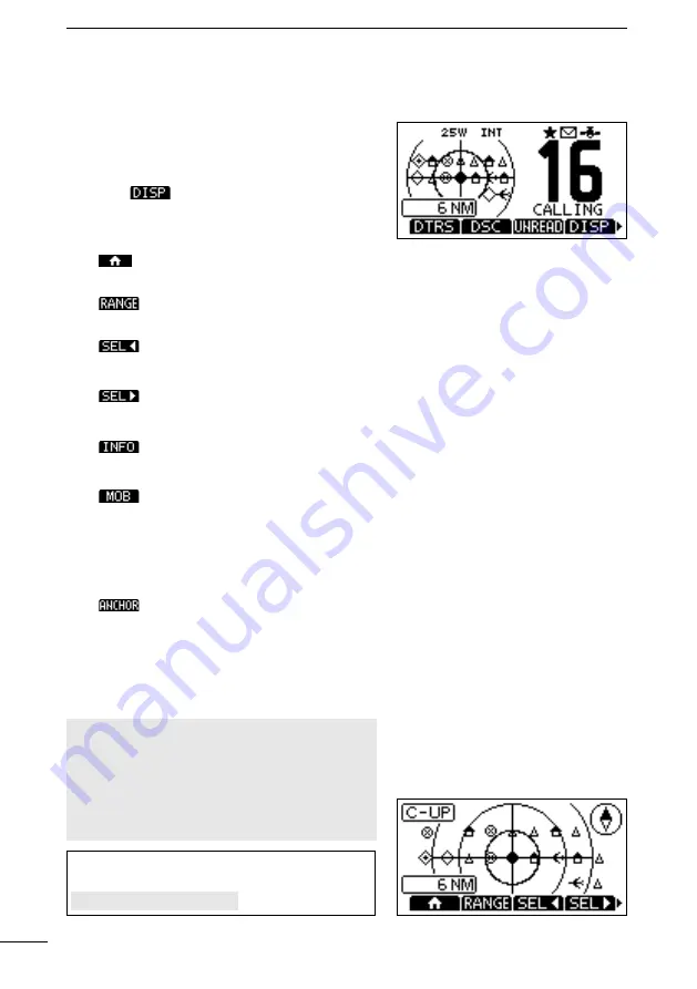
On the plotter screen, the display range, the icons 

of the AIS target, and MOB are displayed. You can 

change the display range and type, depending on 

your operating style.

1.  Push 

 and then select “Plotter”.

 •

The Plotter screen is displayed.

2.  Push the Software Key for your next operation.


:

Returns to the operating 

screen.

:

Selects the display range. 

(p. 54)

:

Selects the closest target to 

your vessel.

:

Selects the farthest target 

from your vessel.

:

Displays the details on the 

selected target. (p. 59)

:

Push to enter the Man 

Overboard (MOB) mode. 

(p. 65)

While in the Man Overboard 

(MOB) mode, push to stop 

the MOB mode.

:

Push to start the Anchor 

watch function. (p. 65)

While in the Anchor watch 

mode, push to stop Anchor 

watch.

NOTE:

 An alarm sounds when an AIS target is 

closer than the CPA (Closest Point of Approach) 

and TCPA (Time to CPA) settings, and so on, 

depending on the presetting. To stop the alarm 

buzzer, push any key.


L

If a popup screen is displayed, push any key 

again to turn it OFF.

TIP

: You can display only the Plotter screen by 

selecting the “Plotter” item on the Menu screen.

[MENU] > AIS > 

Plotter

Summary of Contents for IC-M510BB

Page 1: ...INSTRUCTION MANUAL This device complies with Part 15 of the FCC Rules Operation is subject to the condition that this device does not cause harmful interference VHF MARINE TRANSCEIVER M510BB...

Page 2: ...3 8 V z z IPX7 waterproof 1 m depth water for 30 minutes z z 2 minutes last call voice recording z z Active noise cancelling for transmitted and received audio Important READ ALL INSTRUCTIONS carefull...

Page 3: ...z Say your call sign or other indication of the vessel AND your 9 digit DSC ID if you have one z z LOCATED AT your position z z State the nature of the distress and assistance required z z Give any o...

Page 4: ...antenna when persons are within the MPE radius of the antenna unless such persons such as driver or radio operator are shielded from antenna field by a grounded metallic barrier The MPE Radius is the...

Page 5: ...l antenne lorsque des personnes se trouvent l int rieur du rayon d exposition maximale admissible de cette antenne moins que ces personnes comme le conducteur ou l op rateur radio ne soient prot g es...

Page 6: ...rme la partie 15 de la r glementation FCC Son fonctionnement est soumis la condition que cet appareil ne provoque pas d interf rences nocives Cet quipement a t test et reconnu conforme aux limites fix...

Page 7: ...the transceiver Always disconnect the power source and antenna before a storm R R WARNING NEVER place the transceiver where normal operation of the vessel may be hindered or where it could cause bodil...

Page 8: ...S utiliser ou placer l metteur r cepteur dans des zones o la temperature est inf rieure 20 C 4 F ou sup rieure 60 C 140 F ou dans des zones soumises au rayonnement solaire direct telles le tableau de...

Page 9: ...agnetic field exposure limits 1999 519 EC The maximum RF power available from this device is 25 watts The antenna should be installed as high as possible for maximum efficiency and the installation he...

Page 10: ...your Icom distributor or your dealer for advice Key Icon Description The keys are described in this manual as follows The keys that have words or letters on them are described with the characters Exam...

Page 11: ...viii Recommendation ix Key Icon Description ix 1 OPERATING RULES 1 2 PANEL DESCRIPTION 2 Command microphone 2 Function Display INFO screen 3 Software Keys 5 3 PREPARATION 7 Entering the MMSI code 7 En...

Page 12: ...s 33 Receiving DSC calls other 36 DSC Log 41 Multiple task mode 42 DSC Settings 44 Making an Individual call to an AIS target 46 DSC Remote Control EN 300 338 8 compatible 49 8 AIS FUNCTION 52 About A...

Page 13: ...cting to the MA 510TR 82 Supplied accessories 83 Fuse replacement 83 Mounting the transceiver 84 Microphone installation 85 12 SPECIFICATIONS AND OPTIONS 87 Specifications 87 Dimensions 89 Options 90...

Page 14: ...radio purposes 2 OPERATOR S LICENSE A Restricted Radiotelephone Operator Permit is the license most often held by small vessel radio operators when a radio is not required for safety purposes The Res...

Page 15: ...Key functions p 5 Push to select a character or number in the entry mode p 12 6 ENTER KEY ENT Push to set the entered data selected item and so on 7 CHANNEL 16 CALL CHANNEL KEY 16 C Push to select Cha...

Page 16: ...ing 6 CALL CHANNEL p 12 Displayed when the Call channel is selected 7 DUPLEX Displayed when a Duplex channel is selected 8 FAVORITE CHANNEL p 15 Displayed when a Favorite channel is selected 9 MESSAGE...

Page 17: ...isplayed when valid GPS data is received or the position has been manually entered NO POSITION is displayed when valid GPS data is not received or your position has not been manually entered blinks ev...

Page 18: ...MERGENCY A DISTRESS CALL SHOULD BE MADE ONLY WHEN IMMEDIATE HELP IS NEEDED Compose other DSC DSC p 23 Push to compose an Individual call Group call All Ships call or a Test call and so on Task List TA...

Page 19: ...ction High Low HI LO Push to set the output power level to high or low L L Some channels are set to only low power RX Play PLAY p 67 Push to play back the recorded audio RX Hailer p 69 Push to display...

Page 20: ...f you skip the entry you cannot make a DSC call To enter the code after skipping turn OFF the power and then turn it ON again 3 Enter the MMSI code TIP Select a number using and Push ENT to enter the...

Page 21: ...the selected number Select or or rotate DIAL on the screen to move the cursor 4 Repeat step 3 to enter all 10 digits 5 Select to set the entered ID The ATIS ID CONFIRMATION screen is displayed 6 Enter...

Page 22: ...ed to store your most often used channels in each Channel Group for quick recall See page 12 for details on setting the Call channel Hold down 16 C for 1 second to select the Call channel The Call cha...

Page 23: ...e broadcasts D D Selecting a Weather channel 1 Push CH WX WX is displayed on the operating screen instead of the Channel Group 2 Push or or rotate DIAL to select a Weather channel The Weather channel...

Page 24: ...D Adjusting the backlight The Function display and keys can be backlit for better visibility under low light conditions 1 Open the BACKLIGHT screen MENU Settings Configuration Backlight L You can als...

Page 25: ...n when an external speaker is connected 1 Push or to display 2 Hold down to turn ON the function A low frequency vibration beep sounds to drain the water regardless of the volume level setting L This...

Page 26: ...rophone at your normal voice level is displayed while transmitting 3 Release PTT to receive TIP To maximize the readability of your transmitted signal pause for a second after holding down PTT and hol...

Page 27: ...ough all Favorite channels Channel 16 is not scanned unless it is set as a Favorite channel CH 04 CH 02 CH 03 WX CH 01 CH 05 Priority Scan Sequentially searches through all Favorite channels while als...

Page 28: ...nnels are preset as Favorite channels The preset channels di er depending on the transceiver version Starting a scan Except for the NLD version Example Starting a Normal Scan 1 Select a Channel Group...

Page 29: ...s received on Channel 16 5 To cancel Dualwatch or Tri watch push or again Except for the NLD version Description Dualwatch and Tri watch are convenient to periodically check Channel 16 while you are o...

Page 30: ...Select a number using and Push ENT or DIAL to set the selected number Select or on the screen or rotate DIAL to move the cursor NOTE For a Group ID the first digit is fixed as 0 For any coast station...

Page 31: ...osition date and time If no GPS data is received manually enter the position and Universal Time Coordinated UTC time NOTE The manual entry is disabled while valid GPS data is received The manually ent...

Page 32: ...ks 3 After sending wait for an Acknowledgment call Waiting for ACK is displayed The Distress call is automatically sent every 3 5 to 4 5 minutes until an Acknowledgment is received or a Distress Cance...

Page 33: ...or details 4 While lifting up the key cover hold down DISTRESS the red button for 3 seconds until you hear 3 short countdown beeps and a long beep sound The backlight blinks 5 After sending wait for a...

Page 34: ...down PTT to report the purpose of the cancellation L L You can display the wording of the cancellation by pushing 4 After communicating push L L The screen on the right is displayed 5 Push to finish...

Page 35: ...elay call is received An alarm sounds The screen on the right is displayed 2 Push any to turn OFF the alarm 3 Push The received information is displayed 4 Push The call contents screen is displayed L...

Page 36: ...electing the Compose Other item on the Menu screen 2 Select Type and then push ENT or DIAL 3 Select Individual Call and then push ENT or DIAL Returns to the previous screen 4 Select Address and then p...

Page 37: ...select the Acknowledgment type Able to Comply Sends an Acknowledgment without any changes Unable to Comply Sends an Acknowledgment but cannot communicate Propose New CH Sends an Acknowledgment You can...

Page 38: ...screen 4 Select Category and then push ENT or DIAL The CATEGORY screen is displayed 5 Select a category of the call and the push ENT or DIAL Returns to the previous screen 6 Select Channel and then p...

Page 39: ...turns to the previous screen 4 Select Address and then push ENT or DIAL The ADDRESS screen is displayed 5 Select the group to send a Group call and then push ENT or DIAL L L You can also select Manual...

Page 40: ...cted and returns to the COMPOSE OTHER screen 3 Select Address and then push ENT or DIAL The ADDRESS screen is displayed 4 Select a station to send the Test call to L L You can also select Manual Input...

Page 41: ...ment to the calling station p 44 If the function is set to Manual do the following steps to send an Acknowledgment 1 After a Test call is being received push to turn OFF the alarm 2 Push The received...

Page 42: ...3 Select Position Request and then push ENT or DIAL L L When you send a Polling Request call select Polling Request Returns to the previous screen 4 Select Address and then push ENT or DIAL 5 Select...

Page 43: ...rns to the Main screen Able to Comply Sends Acknowledgment Able to comply right away The call is saved in the DSC Log Displays the Acknowledgment information and then returns to the operating screen b...

Page 44: ...ush or then push to send the Position Reply call Closes the call and then returns to the operating screen Able to Comply Sends an acknowledgment with position and time data Unable to Comply Sends an a...

Page 45: ...turn OFF the alarm 2 Push Enters the DSC Task mode 3 Push The call contents screen is displayed 4 Push to send the Polling Reply Transmitting Polling Reply is displayed 5 Push and then push to return...

Page 46: ...Push to turn OFF the alarm 2 Push the Software Key below the intended operation Returns to the operating screen The call is saved in the DSC Log blinks continuously until you display the call message...

Page 47: ...push to turn OFF the alarm 2 Push The received information is displayed 3 Push The received information is displayed 4 Push Terminate the procedure Are you sure is displayed 5 Push to return to the op...

Page 48: ...lds the RX call task and returns to the Main screen is not displayed if the CH Auto Switch item is set to Manual p 44 Pauses the countdown until the assigned channel is automatically selected The call...

Page 49: ...dividual call is received An alarm sounds RCVD INDIVIDUAL CALL is displayed 1 Push to turn OFF the alarm 2 Push the Software Key below the next operation Ignores the call and returns to the operating...

Page 50: ...ftware Key below your next operation Ignores the call and returns to the operating screen The call is saved in the DSC Log blinks continuously until you display the call message Holds the RX call task...

Page 51: ...to turn OFF the alarm 2 Push the Software Key below the intended operation Ignores the call and returns to the operating screen The call is saved in the DSC Log blinks continuously until you display t...

Page 52: ...perating screen The call is saved in the DSC Log blinks continuously until you display the call message Holds the RX call task and returns to the Main screen Able to comply Sends a Test Acknowledgment...

Page 53: ...eceived An alarm sounds The following screen is displayed and the backlight blinks blinks 1 Push to turn OFF the alarm 2 Push The received information is displayed 3 Push Terminate the procedure Are y...

Page 54: ...call log and Others displays the received DSC call log TIP You can also display the RECEIVED CALL LOG screen by pushing on the operating screen 4 Select a log and then push ENT DIAL or to display the...

Page 55: ...any operation on a task the transceiver automatically deletes a task and returns to the operating screen When a Inactivity Timer activates an alarm sounds and a count down message is displayed for 10...

Page 56: ...number of tasks is displayed at the top of the screen The number of tasks On the TASK LIST screen the following Software Keys are displayed Holds the task and returns to the operating screen Finishes...

Page 57: ...ment Manual Manually sends an Acknowledgment CH Auto Switch Select whether or not to automatically switch to channel 16 or the specified channel or ignore the call Accept after 10 sec After receiving...

Page 58: ...An alarm sounds when duplicate Distress calls are received z z Discrete An alarm sounds when a lower priority call is received while receiving a high priority call CH 70 SQL Level Sets the Squelch le...

Page 59: ...elect Channel then push ENT or DIAL to display the Voice channel selection screen L L See page 23 for details 4 Select a channel to assign and then push ENT or DIAL 5 Push to send the Individual call...

Page 60: ...e already preset into the transponder in the recommended order NOTE When a base station is selected in step 1 a voice channel will be specified by the base station Therefore you cannot change the chan...

Page 61: ...nnel specified in step 4 A different voice channel will be selected if the station you called cannot use the channel To reply push PTT and speak at a normal voice level You can check the MMSI code or...

Page 62: ...er symbols 5 Select and then push ENT or DIAL to save the edited name and return to the previous screen D D Setting the Priority Controller Select which controller to be used as the Priority Controlle...

Page 63: ...s listed below To configure the settings use the Priority Controller Hierarchy Item MENU Settings Configuration Inactivity Timer Not DSC Related DSC Related Distress Related RT Related MENU Settings D...

Page 64: ...operated has Own appended to its name 2 Push or or rotate DIAL to select a controller 3 Push ENT or DIAL to select ON or OFF ON Accepts DSC remote control from the controllers Even when this item is s...

Page 65: ...AR Aids to Navigation AtoN Search and Rescue Transmitter AIS SART Man OverBoard MOB and Emergency Position Indicating Radio Beacon AIS EPIRB AIS There are 2 classes of AIS units which are installed on...

Page 66: ...t from your vessel Displays the details on the selected target p 59 Push to enter the Man Overboard MOB mode p 65 While in the Man Overboard MOB mode push to stop the MOB mode Push to start the Anchor...

Page 67: ...differ depending on the target type or its status Icon Description AIS target Vessel AIS target Search and Rescue SAR vessel L L The tip of the target triangle automatically points in the direction i...

Page 68: ...l Targets All AIS targets are displayed Danger Only Only Danger AIS targets are displayed Friends Only Only Friend AIS Targets are displayed 7 DISPLAY RANGE Displays the selected display range Push to...

Page 69: ...otate DIAL to select an AIS target 5 Push the Software Key below for your next operation Displays the COMPOSE OTHER screen to send an Individual call p 23 L L Displayed only when a target is selected...

Page 70: ...de or name Range RNG from your vessel to the target units NM Bearing BRG from your vessel to the target units degree D D Danger list screen The Danger List screen displays any Danger target whose CPA...

Page 71: ...ting in the Target List or Danger List 1 Open a Target List or a Danger List MENU AIS Target List or Danger List 2 Push or or rotate DIAL to select an AIS target 3 Push to display the details screen T...

Page 72: ...rt side to antenna distance Starboard side to antenna distance Length Beam Draught Type of ship NAV Status Destination Estimated time of arrival Elapsed time Class B AIS class MMSI code Ship name Coun...

Page 73: ...tion Latitude Longitude PA Position Accuracy H High L Low Vendor ID Range Bearing Elapsed time SAR aircraft AIS class MMSI code Target name Country name Call sign Vendor ID Position Latitude Longitude...

Page 74: ...t to turn the following alarm functions ON or OFF ON The alarm function is ON An alarm sounds and a popup screen is displayed L L The alarm may not sound depending on the Audible Alarm setting OFF The...

Page 75: ...om the Danger list p 57 and then re enters the list can a new Slow warn or regular alarm sound depending on the vessel s SOG or CPA and TCPA The Slow warn function operates in the same way if your ves...

Page 76: ...nsponder s ID is displayed No ID is displayed if there is no blocked AIS transponder 2 Push to start the ID entry 3 Enter an ID TIP Select a number using and Push ENT or DIAL to enter the selected num...

Page 77: ...the dark or when you have lost visual contact You can select an AIS target during the MOB mode D D Starting MOB z z Push to enter the MOB mode Three beeps sound The MOB screen is displayed is display...

Page 78: ...ds the range of the anchor watch Exceeded anchor radius is displayed D D Stopping Anchor Watch 1 Push to stop the Anchor Watch mode Deactivate anchor watch Are you sure is displayed 2 Push TIP You can...

Page 79: ...Vessel is at anchor moored and moving faster than 3 knots 60 seconds N A 3 Class A Vessel is moving between 0 and 14 knots Class B Vessel is moving between 2 and 14 knots 60 seconds N A 180 seconds 4...

Page 80: ...reen MENU Settings Radio Voice Record 2 Select Auto Last 120 sec z Recording starts automatically when a signal is received is displayed when recording the received audio The recorded audio is erased...

Page 81: ...the Intercom mode L L ALL is displayed only when 3 command microphones are connected to the transceiver L L The controller being operated has Own appended to its name 3 Hold down to sound the interco...

Page 82: ...speaker must be connected to the transceiver L L See page 82 for details of the connection 1 Push to enter the RX Hailer setting screen 2 Push and then push or or rotate DIAL to set the RX Hailer func...

Page 83: ...nected to the transceiver You cannot transmit while using the hailer 1 Open the Hailer screen MENU Hailer 2 Hold down PTT and speak at your normal voice level While holding down PTT the screen shown o...

Page 84: ...ed by 2 seconds every 120 seconds Sailing vessel underway fishing vessel underway or anchored vessel not under command a vessel restricted in her ability to maneuver underway or at anchor or a vessel...

Page 85: ...to sound a horn While holding down the horn sounds and the screen shown on the right is displayed L L To adjust the horn volume level push to open the Horn Volume popup screen NOTE While in the Horn m...

Page 86: ...displayed L L Holding down or or rotate DIAL sequentially scrolls up or down through the Menu screen 3 Push or or rotate DIAL to select Configuration and then push ENT DIAL or The CONFIGURATION screen...

Page 87: ...Channel Unread List Task List 1 p 43 AIS Plotter p 53 Target List p 57 Danger List Friends List Hailer p 69 Horn Manual Horn p 72 Auto Foghorn p 71 Horn Volume p 72 Frequency p 72 Intercom 2 p 68 MOB...

Page 88: ...14 Scan Timer 4 p 78 Dual Tri Watch 4 p 16 Channel Group p 9 Call Channel p 12 WX Alert 1 p 10 Voice Record p 67 Favorite Channel 4 p 15 Channel Display p 79 LO DX 1 DSC Position Input p 18 Individua...

Page 89: ...and the backlight level Backlight to any one of 4 sequential positions on the Dial UTC Offset Set the offset time between Universal Time Coordinated UTC and your local time to between 14 00 and 14 00...

Page 90: ...to approximately one third OFF The Noise Cancel function is OFF Power Switch Select whether or not to turn OFF the transceiver at the same time that you turn OFF the command microphone z z All Units...

Page 91: ...while operating on another channel Channel Group Select the suitable channel group for your operating area Select USA INT or CAN depending on the transceiver version L L See page 9 for details Call C...

Page 92: ...with its plug and play functionality and display the information provided from the devices on the network Select the sensors in NMEA 2000 network which sends data to the transceiver L L See the next p...

Page 93: ...9810 AIS Class B CS Static Data Report Part B Transmit 059392 ISO Acknowledgment 059904 ISO Request 060416 ISO Transport Protocol Connection Management 060928 ISO Address Claim 126208 NMEA Acknowledge...

Page 94: ...Listener B Data L Data In Connect to the NMEA output lines of a GPS receiver or an AIS device for position data NMEA 0183 ver 2 0 or later sentence format RMC GGA GNS or GLL and VTG compatible GPS re...

Page 95: ...ter connecting the DC power cable NMEA leads or external speaker leads cover the connector and leads with a vulcanizing tape as shown below to prevent water seeping into the connection 8 GROUND TERMIN...

Page 96: ...problem repair it and replace the damaged fuse with a new one of the proper rating Fuse Coding explanation Fuse Coding F 250 V 10 A Fuse Voltage Rating 250 Volts Fuse Current Rating 10 Amperes Command...

Page 97: ...than 5 kg 11 lb using the 4 supplied screws 5 20 mm as illustrated below CAUTION KEEP the transceiver and microphone at least 1 meter 3 3 ft away from the vessel s magnetic navigation compass NOTE Be...

Page 98: ...icrophones may be updated when you connect them to the transceiver D D Installation 1 Insert the connection cable connector into the command microphone jack and tighten the nut 2 To use the cable conn...

Page 99: ...86 1 7 4 10 15 18 2 8 13 5 11 16 3 9 14 6 12 17 CONNECTIONS 11 Gasket Mounting base Cap Nut 50 d 131 32 5 3 16 unit mm inch 2 3 32 28 d 13 32 29 5 to 31 5 d 15 32 to 11 4...

Page 100: ...mum frequency deviation 5 kHz Spurious emissions Less than 70 dBc High Power Less than 56 dBc Low Power Frequency tolerance 0 5 kHz Adjacent channel power More than 70 dB Audio harmonic distortion Les...

Page 101: ...uency modulation Maximum frequency deviation 5 kHz Spurious emissions Less than 0 25 W Frequency error Less than 0 5 kHz Adjacent channel power More than 70 dB Audio harmonic distortion Less than 10 a...

Page 102: ...ch Calculation Maximum 12 ch Differential satellites WAAS EGNOS MSAS GAGAN Corresponding GPS GPS GLONASS SBAS Receiving frequency GPS SBAS 1575 42 MHz GLONASS 1602 00 MHz D D NMEA 2000 Load Equivalenc...

Page 103: ...one extension cable for optional HM 195 Up to two OPC 1541 can be connected Usable length is 18 meters 60 feet maximum SP 37 horn speaker The external horn speaker Connect with the AF Out leads for th...

Page 104: ...ct The first digit must be set to between 1 and 9 for an Individual ID Enter a correct ID code p 17 blinks instead of the position and time z z Four hours have passed since you manually entered the po...

Page 105: ...respond z z A software error has occurred Turn OFF the transceiver and then turn it ON again The transceiver does not work z z The transceiver s Phase Lock Loop is unlocked Contact your dealer The col...

Page 106: ...400 156 400 09 09 09 156 450 156 450 10 10 10 156 500 156 500 11 11 11 156 550 156 550 12 12 12 156 600 156 600 13 1 3 13 13 1 156 650 156 650 14 14 14 156 700 156 700 15 2 3 15 1 15 1 156 750 156 750...

Page 107: ...156 575 72 72 72 156 625 156 625 73 73 73 156 675 156 675 74 74 74 156 725 156 725 75 1 75 1 156 775 156 775 76 1 76 1 156 825 156 825 77 1 77 77 1 156 875 156 875 78 156 925 161 525 1078 1078 1078 1...

Page 108: ...power only for the NLD version 5 For only the NLD and UK versions 6 For only the NLD version 7 For only the UK version L L 1037 and P4 channels are UK Marina Channels M1 1037 M2 P4 for only the UK ver...

Page 109: ...9 Name 14 Selecting 9 Channel 16 9 Channel Display Radio Settings 79 Channel Group Radio settings 78 CH Auto Switch DSC Settings 44 Command microphone COMMANDMIC Speaker 77 Display Contrast 76 Menu sc...

Page 110: ...ual Acknowledgment Sending 24 Individual call Receiving 36 Sending 23 Individual ID Deleting 18 DSC Settings 44 Entering 17 Intercom 68 K Key Assignment Configuration 76 Key Beep Configuration 76 L Li...

Page 111: ...re DSC Settings 45 R Radio Info 80 Receiving 13 RX Hailer 69 Configuration 77 S Scan Priority 14 Starting 15 Types 14 Scan Timer Radio settings 78 Scan Type Radio settings 78 Self Check Test DSC Setti...

Page 112: ...1 1 32 Kamiminami Hirano ku Osaka 547 0003 Japan A7732D 1EX Printed in Japan 2023 Icom Inc Mar 2023 How the World Communicates...

Reviews: