R9
R10
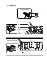
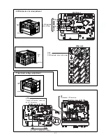
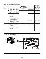
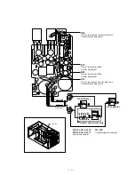
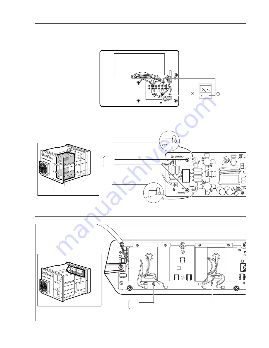
• Idling current pre-setting
• Idling current adjustment
L6
PA1–PA4 boards
Connect the lead of L6 to ground
L5
Connect the lead of L5
to ground
4 - 3
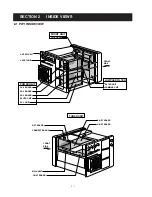
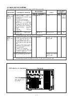
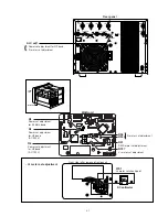
Front side (after removed front panel)
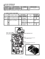
Ammeter
WS1
I
D
ALC and I
D
meter check point
R56
R57
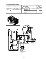
Meter maximum point adjustment
Switch board
FRONT
SIDE
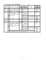
PA-1 BOARD
PA-2 BOARD
PA-3 BOARD
PA-4 BOARD
SW BOARD
FRONT
SIDE
• Idling current adjustment
• Meter maximum point adjustment
Summary of Contents for IC-PW1
Page 1: ...SERVICE MANUAL ADDENDUM CONTENTS PARTS LIST 1 BOARD LAYOUTS 16 VOLTAGE DIAGRAM 18 Mar 2011 ...
Page 24: ...SERVICE MANUAL ADDENDUM CONTENTS PARTS LIST 1 BOARD LAYOUTS 16 Jun 2010 ...
Page 42: ...SERVICE MANUAL ADDENDUM CONTENTS PARTS LIST 1 BOARD LAYOUTS 16 VOLTAGE DIAGRAM 18 Apr 2010 ...
Page 96: ...HF 50 MHz ALL BAND LINEAR AMPLIFIER iC PW1 ...
Page 175: ...MNF F1 EP2 TO REGRELAY BOARD MLF EP1 F2 TO REGRELAY BOARD EP35 I N FG 8 19 FIL AC BOARD 8 20 ...
Page 201: ...A 5449MZ S 3 1999 Icom Inc 1 1 32 Kamiminami Hirano ku Osaka 547 0003 Japan Count on us ...

