background image

17

6

INFORMATION


FCC Information

This equipment has been tested and found to 

comply with the limits for a Class B digital device, 

pursuant to part 15 of the FCC Rules. These limits 

are designed to provide reasonable protection against 

harmful interference in a residential installation. This 

equipment generates, uses and can radiate radio 

frequency energy and, if not installed and used in 

accordance with the instructions, may cause harmful 

interference to radio communications. However, there 

is no guarantee that interference will not occur in a 

particular installation. If this equipment does cause 

harmful interference to radio or television reception, 

which can be determined by turning the equipment 

off and on, the user is encouraged to try to correct 

the interference by one or more of the following 

measures:

 • Reorient or relocate the receiving antenna.

 • Increase the separation between the equipment 

and receiver.

 • Connect the equipment into an outlet on a 

circuit different from that to which the receiver is 

connected.

 • Consult the dealer or an experienced radio/TV 

technician for help.

CAUTION: 

Changes or modifications to this device, 

not expressly approved by Icom Inc., could void 

your authority to operate this device under FCC 

regulations.


Information FCC

Cet équipement a été testé et reconnu conforme aux 

limites fixées pour un appareil numérique de classe B, 

conformément au point 15 de la réglementation FCC. 

Ces limites ont été fixées afin d’assurer une protection 

raisonnable contre les interférences nocives dans 

une installation résidentielle. Cet équipement génère, 

utilise et peut émettre un rayonnement de fréquence 

radio. S’il n’a pas été installé conformément aux 

instructions, il peut par ailleurs créer des interférences 

perturbant les communications radio. Toutefois, il 

n’y a aucune garantie que les interférences ne se 

produiront pas dans une installation particulière. Si 

cet équipement crée des interférences perturbant 

la réception de la radio ou de la télévision, comme 

cela peut être déterminé en éteignant et en allumant 

l’équipement, l’utilisateur est invité à essayer de 

corriger l’interférence en prenant une ou plusieurs des 

mesures ci-après:

•  Réorienter ou changer de place l’antenne de 

réception.

•  Éloigner l’équipement et le récepteur.

•  Connecter l’équipement sur une prise sur un autre 

circuit que celui sur lequel le récepteur est connecté.

•  Faire appel au revendeur ou à un technicien radio/

TV expérimenté.

MISE EN GARDE: 

Tout changement ou modification, 

non expressément approuvé par Icom Inc, peut 

annuler l’autorisation de l’utilisateur à utiliser cet 

appareil conformément à la réglementation FCC.


About the licences

License for CMSIS-RTOS RTX Implementation

Copyright (c) 1999-2009 KEIL, 2009-2013 ARM Germany GmbH All rights reserved.

Redistribution and use in source and binary forms, with or without modification, are permitted provided that the following conditions are met:

 -   Redistributions of source code must retain the above copyright notice, this list of conditions and the following disclaimer.

 -  Redistributions in binary form must reproduce the above copyright

    notice, this list of conditions and the following disclaimer in the documentation and/or other materials provided with the distribution.

 -  Neither the name of ARM  nor the names of its contributors may be used

    to endorse or promote products derived from this software without specific prior written permission.

THIS SOFTWARE IS PROVIDED BY THE COPYRIGHT HOLDERS AND CONTRIBUTORS “AS IS” AND ANY EXPRESS OR IMPLIED 

WARRANTIES, INCLUDING, BUT NOT LIMITED TO, THE IMPLIED WARRANTIES OF MERCHANTABILITY AND FITNESS FOR A 

PARTICULAR PURPOSE ARE DISCLAIMED. IN NO EVENT SHALL COPYRIGHT HOLDERS AND CONTRIBUTORS BE LIABLE FOR 

ANY DIRECT, INDIRECT, INCIDENTAL, SPECIAL, EXEMPLARY, OR CONSEQUENTIAL DAMAGES (INCLUDING, BUT NOT LIMITED 

TO, PROCUREMENT OF SUBSTITUTE GOODS OR SERVICES; LOSS OF USE, DATA, OR PROFITS; OR BUSINESS INTERRUPTION) 

HOWEVER CAUSED AND ON ANY THEORY OF LIABILITY, WHETHER IN CONTRACT, STRICT LIABILITY, OR TORT (INCLUDING 

NEGLIGENCE OR OTHERWISE) ARISING IN ANY WAY OUT OF THE USE OF THIS SOFTWARE, EVEN IF ADVISED OF THE POSSIBILITY 

OF SUCH DAMAGE.

Summary of Contents for ID-RP2010V

Page 1: ...s with part 15 of the FCC Rules Operation is subject to the condition that this device does not cause harmful interference INSTRUCTION MANUAL VHF REPEATER ID RP2010V UHF REPEATER ID RP4010V 1 2 GHz RE...

Page 2: ...ice coding Technology is licensed solely for use within this Communications Equipment The user of this Technology is explicitly prohibited from attempting to extract remove decompile reverse engineer...

Page 3: ...jury or damage the repeater CAUTION DO NOT expose the repeater to rain snow or any liquids They could damage the repeater CAUTION DO NOT use or leave the repeater in areas with temperatures below 10 C...

Page 4: ...ilement l antenne tout en trans mettant Cela pourrait causer un choc lectrique ou des brulures R R AVERTISSEMENT NE JAMAIS raccorder de courant alternatif la prise DC13 8V sur le panneau arri re de le...

Page 5: ...C 8 Operating as a Gateway 9 D D Using a Gateway server 9 D D System requirements 9 4 SD CARD 10 Using an SD card 10 D D Inserting 10 D D Removing 10 About the SD card s folder contents 11 5 MAINTENAN...

Page 6: ...server Internet LTE network Area Area Area Area Assist network Trust server Internet Gateway server Zone Repeater Assist repeater ID RP2C ID RP2L Repeater Assist repeater Gateway server Internet ID RP...

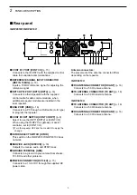
Page 7: ...system does not work if it is connected to other repeaters 7RESET SWITCH The switch used for special operation such as resetting the repeater and so on L LPush using the tip of the pen L LThe switch i...

Page 8: ...set to CONT I O L LTurn the repeater OFF and then restart it to apply the change 6DV DD SELECT SWITCH DV DD This switch on the ID RP2010V ID RP4010V does not work 7SERVICE JACK SERVICE p 16 Outputs t...

Page 9: ...SWITCH CONT I O RPT p 8 Select to use the RPT1 RPT2 or CONT I O When using the ID RP2C as gateway or assist controller set to CONT I O L LTurn the repeater OFF and then restart it to apply the change...

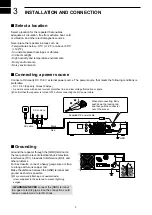
Page 10: ...V external power source The power source that meets the following conditions is preferable DC 13 8 V Capacity At least 9 Amps A power source with an over current protective line and low voltage fluctu...

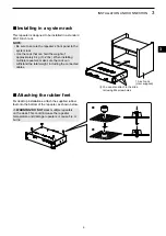
Page 11: ...ately 6 kg 13 2 lbs When installing multiple repeaters make sure the rack can withstand the total weight including the connected cables 19 inch rack User supplied L LYou can also attach to the slide r...

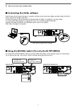
Page 12: ...RP1200VD ID RP2010V ID RP4010V Connecting the Utility software Sets the transmit and receive frequency repeater call sign and other function settings using the Utility for ID RP3 Ask your dealer for...

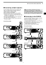
Page 13: ...ONT I O RPT CONT I O RPT LAN cable RPT1 RPT2 LAN cable RPT1 RPT2 ID RP1200VD DD mode ID RP1200VD DV mode DD DV DD DV Connecting to the ID RP2C Connect the ID RP2C Repeater controller and assist repeat...

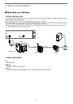
Page 14: ...ter Gateway server and router as shown below Ask your dealer for details of settings required for the Gateway server and router L LOnly one repeater can be used as a Gateway if multiple repeaters are...

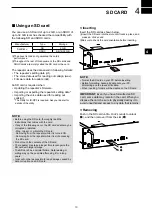
Page 15: ...PC Formatting a card erases all its data When inserting folders will be created on the SD card IMPORTANT Even if you have formatted an SD card some data may remain in the card When you dispose the ca...

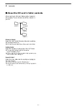
Page 16: ...s setting data will be saved as SetYYYYMMDD_XX icf L LWhen writing the programmed data to the repeater save it with the file name Setting icf Speech folder Saves the voice data used for reading out ca...

Page 17: ...A ID RP4010V ID RP1200VD Circuitry fuse APS 5 A 1 2 3 RWARNING NEVER use fuses that are not specified It may damage the repeater or cause fire Disconnect the DC power cable from the repeater before re...

Page 18: ...oblems Check and if necessary replace the coaxial cable or the antenna connector There was a problem with the operation Caused by external factors such as static electricity Turn OFF the repeater remo...

Page 19: ...0V ID RP1200VD 9 0 A or less TX High 4 0 A or less TX Low 1 8 A or less Standby 7 0 A or less TX High 3 0 A or less TX Low 1 8 A or less Standby 6 0 A or less TX High 4 0 A or less TX Low 1 8 A or les...

Page 20: ...1LINK ACT Lights when a cable is connected Does not light when a cable is not connected Blinks while communicating 2SPEED Lights while communicating in 100BASE TX Does not light while communicating B...

Page 21: ...ta Output impedance 4 8 Output level More than 2 W at 10 distortion into an 8 load D D TX ANT Connect a TX antenna Type N Input impedance 50 unbalanced L LIn DD mode of the ID RP1200VD the connector i...

Page 22: ...io ou de la t l vision comme cela peut tre d termin en teignant et en allumant l quipement l utilisateur est invit essayer de corriger l interf rence en prenant une ou plusieurs des mesures ci apr s R...

Page 23: ...MEMO...

Page 24: ...1 1 32 Kamiminami Hirano ku Osaka 547 0003 Japan A7595H 1EX 3 Printed in Japan 2020 2022 Icom Inc Apr 2022 How the world communicates...

Reviews: