background image

9

2

INSTALLATION AND CONNECTIONS

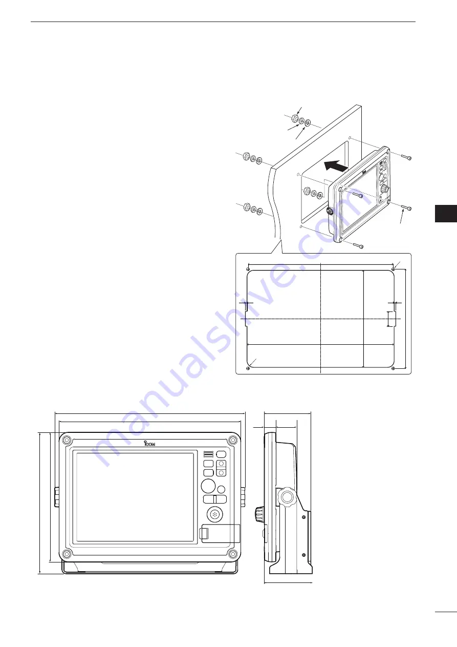
• Dimensions

Flat washer
Spring washer

357.6 (14.08)

353 (13.9)

235.6 (9.28

)

241 (9.49)

Nut

Mounting bolt 
(M6×35 mm)

2 (0.08)

R16 (0.63)

ø7 (0.28)

36 (1.42)

2 (0.08)

D


Wall mounting 

The  display  unit  can  be  mounted  to  a  flat  surface, 
such as an instrument panel, using the mounting bolts 
(M6×35 mm).

q

  Remove the four bolts from the four corners of the 

display unit.

w

  Carefully  cut  a  hole  in  the  instrument  panel,  or 

wherever you plan to mount the display unit.

e

  Drill four holes for the mounting screw.

r

  Slide the display unit through the hole.

t

  Attach the four corners of the display unit using the 

supplied  flat  washers,  spring  washers,  nuts  and 
mounting bolts (M6×35 mm).

404 (15.91)

274 (10.79)

386 (15.2)

299 (11.77)

24.5

(0.96)

44.7

(1.76)

99 (3.9)

102 (4.02)

1
2
3
4
5
6
7
8
9
10
11
12
13
14
15
16
17
18
19
20
21

Unit: mm (inch)

Unit: mm (inch)

Summary of Contents for MarineCommander MXD-5000

Page 1: ...This device complies with Part 15 of the FCC Rules Opera tion is subject to the following two conditions 1 this device may not cause harmful interference and 2 this device must accept any interference received including interference that may cause undesired operation ...

Page 2: ...M4 2 Spring washers M4 2 FCC INFORMATION FOR CLASS A UNINTENTIONAL RADIATORS This equipment has been tested and found to comply with the limits for a Class A digital device pursuant to part 15 of the FCC Rules These limits are designed to provide reasonable protection against harmful interference when the equipment is operated in a commercial environment This equipment generates uses and can radia...

Page 3: ...LLATION AND CONNECTIONS 6 11 Connection 6 Mounting the Main unit 7 Power source requirement 7 Ground connection 7 Installing the Display unit 8 Front cover attachment 10 Bolt cap attachment 10 Removing or connecting the EX 3187 s cable 11 3 MAINTENANCE AND OPTIONS 12 Periodic maintenance 12 Fuse replacement 12 Options 12 4 SPECIFICATIONS 13 5 CONNECTOR INFORMATION 14 1 2 3 4 5 6 7 8 9 10 11 12 13 ...

Page 4: ...nection is made after cutting the Main unit may be damaged R WARNING NEVER open the bottom cover of the Main unit There are no user adjustment points This may result in an electric shock and incorrect reas sembly may cause a fire hazard DO NOT place the Main unit in excessively dusty en vironments KEEP the Main unit away from heavy rain and never immerse it in the water The Main unit meets IPX4 re...

Page 5: ...yBLACK BOX CONNECTORS Connector 1 to 3 Connect a black box unit such as an MXR 5000R T Radar unit an MXF 5000 Fish finder unit or another MXP 5000 Main unit Connector 4 Not used If you connect an MXR 5000R T or MXF 5000 to this connector these units will not operate uVIDEO IN CONNECTORS Four video inputs such as onboard cameras can be connected An RCA type connector is used for these connectors NT...

Page 6: ...B point Position and bearing data are neces sary Hold down MOB for 3 seconds to cancel the func tion e RANGE UP DOWN SWITCHES Push or to set a suitable screen range r FOCUS DISPLAY LAYOUT SWITCH FOCUS LAYOUT Push to change the active screen An orange border indicates the active screen Hold down for 3 seconds to open the display se lection screen t UP DOWN LEFT RIGHT KEYS Ù Ú Ω Push arrow Ù Ú Ω or ...

Page 7: ...reen Quick Menu 2 includes the GAIN SEA RAIN Radar TX menu and Heading line OFF functions On the Sounder screen Quick Menu 2 includes the GAIN 50kHz GAIN 200kHz STC 50kHz and STC 200kHz control func tions 1 SD CARD PORT Insert an SD Card which contains C MAP MAX chart by JEPPESEN Chart data is not supplied by Icom An unmount operation should be performed before removing the SD Card If you do not u...

Page 8: ...s invalid the position data is shown in red for 1 minute After 1 minute has passed invalid data will appear ePALETTE2 Shows various information Default COG Shows your vessel s course over ground T shows true north bearing and M shows magnetic north bearing rPALETTE3 Shows various information Default SOG Shows your vessel s speed over ground If no speed data is found will appear tPALETTE4 Shows var...

Page 9: ...unit 1FISH FINDER ICON Display as an animation when a companion Icom fish finder is connected and operating Appears but not as an animation when the fish finder is connected but not operating An X appears on the icon when the fish finder is not connected to the main unit 2AIS UNIT ICON Appears but with an X below the icon when the AIS unit is not connected to the Main unit The X disappears when an...

Page 10: ...Ground 12 V 24 V battery White Black Green Thinner Black KEEP the terminal guard attached after connecting the cable NOTE Use crimp or solder terminals for the wire connections Solder Crimp Radar unit MXR 5000R T Fish Finder unit MXF 5000 to connectors 1 2 or 3 GPS receiver MXG 5000 Display unit MXD 5000 Display unit MXD 5000 EX 3187 Display extension unit 5 m 16 4 ft 5 m 16 4 ft 5 m 16 4 ft Main ...

Page 11: ...13 14 15 16 17 18 19 20 21 Power source requirement CAUTION Before connecting the DC power cable check the following important items Make sure Output voltage of the power source is 12 V 24 V DC DC power cable polarity is correct White Positive terminal Black Negative _ terminal Green Ground Main unit side is thinner black Fuse rating of the DC power cable is correct The 15 A fuse is pre installed ...

Page 12: ...fter installation Select a location which can support the weight of the display unit DO NOT select areas subject to extreme heat cold vibrations or direct sunlight D Mounting The mounting bracket supplied with the display unit al lows dashboard or overhead mounting q Hold the mounting bracket up to the selected loca tion and mark pilot holes for the five installation bolts w Drill five holes accor...

Page 13: ...the four bolts from the four corners of the display unit w Carefully cut a hole in the instrument panel or wherever you plan to mount the display unit e Drill four holes for the mounting screw r Slide the display unit through the hole t Attach the four corners of the display unit using the supplied flat washers spring washers nuts and mounting bolts M6 35 mm 404 15 91 274 10 79 386 15 2 299 11 77 ...

Page 14: ...Front cover attachment The supplied front cover can be attached to the front of the display unit Front cover Bolt cap attachment The supplied bolt caps can be attached to the four corner bolts to protect them from dust and moisture Cap ...

Page 15: ...side nut Ferrite EMI filter Ferrite EMI filter CAUTION NEVER cut the display cable or display extension cable NOTE About Display Cable The Display cable can also be removed to install it through a hole in a wall After installing the cable through the hole replace the Sealing Nut in the same order as described to the left To install the display cable though a hole in a wall where as the display con...

Page 16: ...to the MarineCommander MXA 5000 ais receiver Allows you to receive other vessel s information such as the vessel name MMSI code vessel type position data speed course destination and more MXG 5000 gps receiver Allows you to receive GPS information OPC 1895 connection cable Allows you to connect the Icom MarineCommander system 20 m 65 6 ft Fuse rating 15 A for 12 V power source 7 5 A for 24 V power...

Page 17: ... consumption Less than 1 0 A at maximum brightness Usable temperature range 20 C to 60 C 4 F to 140 F Dimensions without Bracket 386 W 274 H 69 2 D mm 15 2 W 10 8 H 2 7 D in with Bracket 404 W 299 H 102 D mm 15 9 W 11 8 H 4 0 D in Cable length Approximately 5 m 16 4 ft Weight without Bracket Approximately 3 6 kg 7 9 lb with Bracket Approximately 4 1 kg 9 0 lb All stated specifications are subject ...

Page 18: ...AIS 1 IN Grey Black 1 15 AIS COMMON Common line for AIS 2 Port 4 VHF Orange Black 2 19 DSC IN Input level Less than 2 mA with 2 V applied DSC DSE PICOA Connects to the NMEA input output con nector of a transceiver to transmit an In dividual DSC call The data communication speed baud rate can be selected between 4800 bps 9600 bps and 19200 bps for each Input Output port Default 4800 bps Orange Red ...

Page 19: ...15 MEMO 1 2 3 4 5 6 7 8 9 10 11 12 13 14 15 16 17 18 19 20 21 ...

Page 20: ...1 1 32 Kamiminami Hirano ku Osaka 547 0003 Japan A 6755H 1EX Printed in Japan 2011 Icom Inc ...

Reviews: