5
14
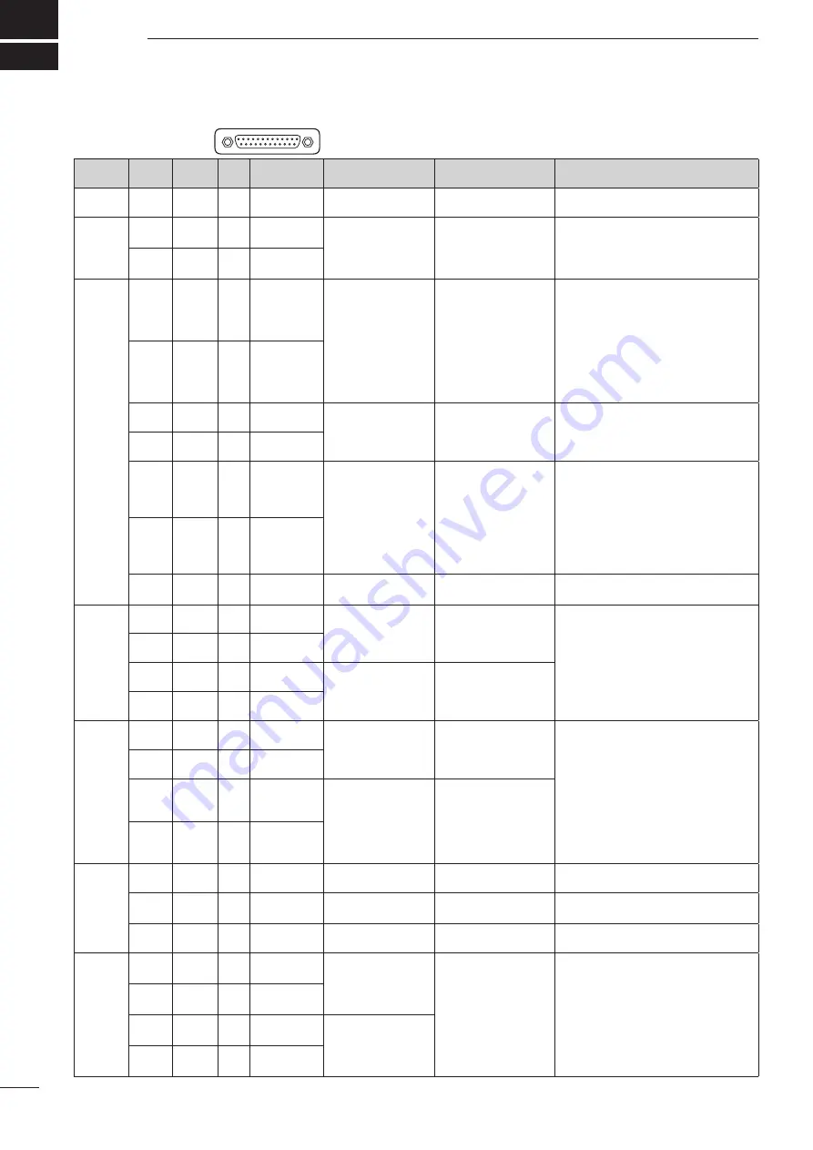
CONNECTOR INFORMATION
DATA IN/OUT
Port
Cable
Color
Line/
Color
Pin
No
Pin Name
Specifications
Sentence Format
Description
13
SGND
—
—
Connects to ground.
Port 2
(Heading)
Pink
Black 2
(– –)
23
HEADING IN
(–)
• Input level
: Less than 2 mA
(with 2 V applied)
HDG, HDT, HDM, THS
Connects to a heading sensor.
The data communication speed (baud rate)
can be selected between 4800 bps, 9600
bps and 19200 bps. (Default: 4800 bps)
Pink
Red 2
(– –)
10
HEADING IN
(+)
Port 3
(AIS)
Yellow Black 1
(–)
17
AIS-2 IN (–)
• Input level
: Less than 2 mA
( RS-422 balanced
type)
GGA, GNS, GLL, GSA,
GSV, RMC, VDM, VTG,
ZDA, ALR
Connects to the Icom MA-500TR or to the
Icom MXA-5000 or to an AIS receiver.
(IEC61162-2)
The data communication speed (baud rate)
can be selected between 4800bps, 9600
bps, 19200 bps and 38400 bps. (Default:
38400 bps)
• When AIS-2 IN is used, the AIS-1 IN can-
not be used.
Yellow
Red 1
(–)
4
AIS-2 IN (+)
Pink
Black 1
(–)
18
AIS OUT (–)
• Output level
: 5 V/40 mA maximum
( RS-422 balanced
type)
GNS, GLL, HDT, RMC
Combines with AIS-2 IN (IEC61162-2) or
AIS-1 IN (IEC61162-1).
Pink
Red 1
(–)
5
AIS OUT (+)
White
Black 1
(–)
16
AIS-1 IN (–)
• Input level
: Less than 2 mA
(with 2 V applied)
GGA, GNS, GLL, GSA,
GSV, RMC, VDM, VTG,
ZDA, ALR
Connects to an AIS receiver.
(IEC61162-1)
The data communication speed (baud
rate) is selectable between 4800 bps,
9600 bps, 19200 bps and 38400 bps.
(Default: 38400 bps)
• When AIS-1 IN is used, the AIS-2 IN
cannot be used.
White
Red 1
(–)
3
AIS-1 IN (+)
Grey
Black 1
(–)
15
AIS
COMMON
—
—
Common line for AIS-2.
Port 4
(VHF)
Orange Black 2
(– –)
19
DSC IN (–)
• Input level
: Less than 2 mA
(with 2 V applied)
DSC, DSE, $PICOA
Connects to the NMEA input/output con-
nector of a transceiver to transmit an In-
dividual DSC call.
The data communication speed (baud
rate) can be selected between 4800 bps,
9600 bps and 19200 bps for each Input/
Output port. (Default: 4800 bps)
Orange Red 2
(– –)
6
DSC IN (+)
Grey
Black 2
(– –)
20
DSC OUT (–) • Output level
: 5 V/40 mA maximum
( RS-422 balanced
type)
DSC, DSE, GGA, GNS,
GLL, RMC, $PICOA
Grey
Red 2
(– –)
7
DSC OUT (+)
Port 5
(General
Purpose)
White
Black 2
(– –)
21
NMEA IN (–) • Input level
: Less than 2 mA
(with 2 V applied)
GGA, GNS, GLL, GSA,
GSV, HDG, HDT, HDM,
MWV, RMC, THS, VHW,
VTG, ZDA
Connects to a piece of navigation equip-
ment.
The data communication speed (baud
rate) can be selected between 4800 bps
9600 bps and 19200 bps for each Input/
Output port. (Default: 4800 bps)
White
Red 2
(– –)
8
NMEA IN (+)
Yellow Black 2
(– –)
22
NMEA OUT
(–)
• Output level
: 5 V/40 mA maxi-
mum
APB, BWC, BWR, DBT,
DPT, GGA, GNS, GLL,
HDG, HDT, MTW, MWV,
RMA, RMB, RMC, TTM,
VHW, VTG, WPL, XTE,
ZDA
Yellow
Red 2
(– –)
9
NMEA OUT
(+)
ALM
Gray
Red 1
(–)
2
ALM CLOSE
—
—
Disconnects between pins 2 and 14 when
the alarm buzzer sounds.
Orange Black 1
(–)
14
ALM
COMMON
—
—
Common relay for the alarm buzzer
Orange Red 1
(–)
1
ALM OPEN
—
—
Pins 1 and 14 are connected together when
the alarm buzzer sounds.
AUX
Gray
Black 3
(– – –)
25
AUX DATA IN
(–)
• Input level
: Less than 2 mA
(with 2 V applied)
HDT, HDM
AUX format
Gray
Red 3
(– – –)
12
AUX DATA IN
(+)
Orange Black 3
(– – –)
24
AUX CLOCK
IN (–)
• Input level
: Less than 2 mA
(with 2 V applied)
Orange Red 3
(– – –)
11
AUX CLOCK
IN (+)
13
1
14
25


