


60
14
INSTALLATION AND CONNECTIONS
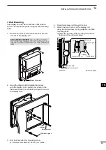
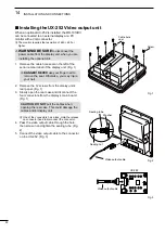
6.
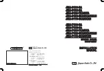
Install the UX-252 on the display’s main board
using the four screws supplied with the UX-252.
(Fig. 4)
•Before tightening the screws, be sure to connect the
UX-252’s connector to the display unit’s connector.
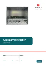
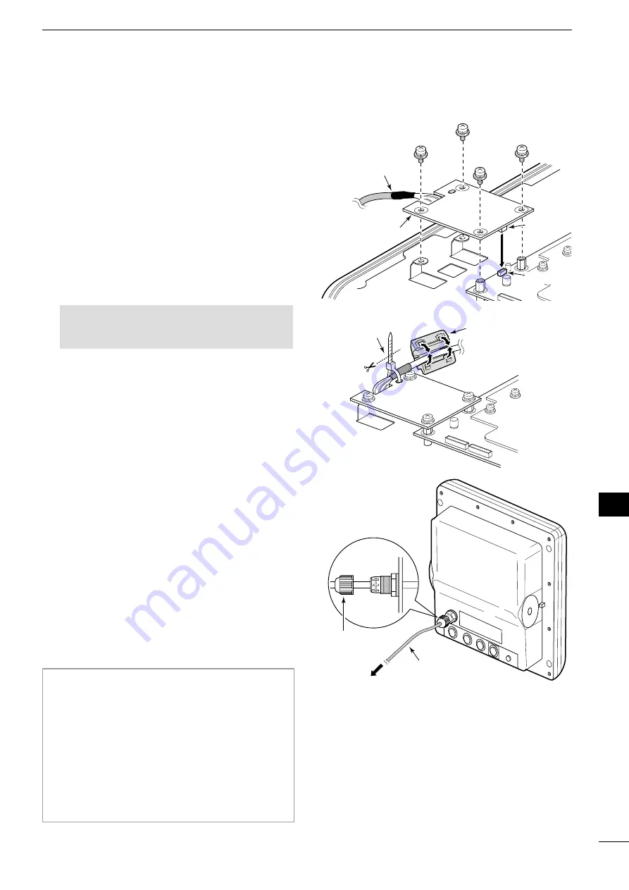
7.
Secure the cable to the UX-252 with a cable tie.
(Fig. 5)
8.
Clamp the cable with the ferrite EMI filter
attached near the UX-252. (Fig. 5)
L
Be sure to clamp it tightly.
9. Reconnect the four connectors to the display’s
main board.
10. Replace the gasket, rear case, and screws their
original position.
L
Make sure the gasket is properly seated.
CAUTION: DO NOT
pinch the cables when
closing the rear case. This could damage the
cables
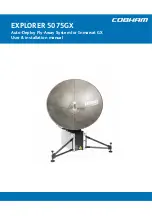
11. Adjust the video output cable length and then
tighten the sealing nut. (Fig. 6)
UX-252
Video output cable
Connector
Connector
Fig. 4
UX-252
Ferrite EMI filter
Cable tie
Fig. 5
Video output cable
Sealing nut
Fig. 6
1
2
3
4
5
6
7
8
9
10
11
12
13
14
15
16
17
18
19
20
21
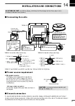
■
Checking the installation
Before turning ON the power, be sure that the display
unit and the scanner unit are installed correctly. The
checklist below may help you.
Installation checklist
•
The four bolts securing the scanner unit must be firmly
tightened.
• Cabling must be securely attached to a mast or
mounting material, and must not interfere with the
rigging.
•
Be sure waterproofing procedures are completed on the
system cable.
•
The power connections to the battery must be of the
correct polarity.
• Be sure that the plugs at the rear of the display unit have
been connected correctly and securely.