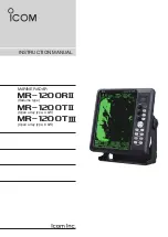
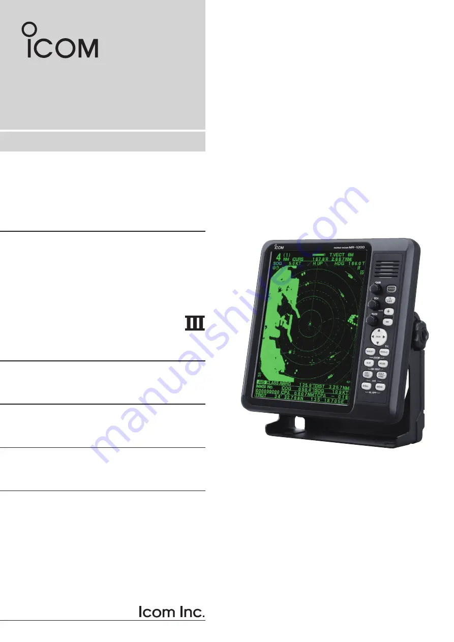
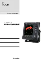
Icom MR-1200RII, Instruction Manual
The Icom MR-1200RII Operating Manual is a comprehensive guide designed for users of this exceptional product. This manual can be downloaded for free from our website, offering step-by-step instructions to maximize the functionality of your device. Explore and download this valuable resource from 88.208.23.73:8080 today!
Share
Download
Reviews:
No comments
Related manuals for MR-1200RII
iNetVu 7000 Series
Brand: C-Com Pages: 18
804Mesh
Brand: Calix Pages: 9
GMR 404
Brand: Garmin Pages: 26
GMR 18
Brand: Garmin Pages: 2

GMR 18
Brand: Garmin Pages: 2
GMR 404
Brand: Garmin Pages: 2
MR-1010RII
Brand: Icom Pages: 72
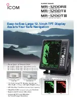
MR-1200RII
Brand: Icom Pages: 2
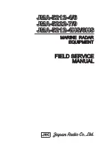
JMA-5212-4
Brand: Japan Radio Co. Pages: 20
JMA-7122-6XA
Brand: JRC Pages: 316
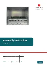
CSE 2800
Brand: Triax Pages: 24
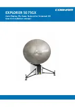
EXPLORER 5075
Brand: COBHAM Pages: 72
Halo20
Brand: Simrad Pages: 32
MR-1000R2
Brand: Icom Pages: 47
1932 MARK-2
Brand: Furuno Pages: 2

GMR 620 xHD2 Series
Brand: Garmin Pages: 8
GMR 404 xHD Open Array and Pedestal
Brand: Garmin Pages: 6

JMA-7100
Brand: JRC Pages: 8


