


8
INSTALLATION AND CONNECTIONS
28
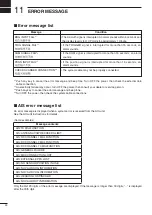
■
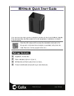
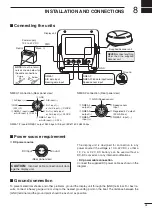
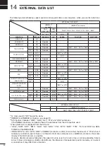
Connecting the units
NMEA2:
NMEA 0183 data input/output
Speed sensor input
+
Ground
Power supply
10.2 to 42 V DC
Red:
Black:
_
PWR
GND
NEVER
connect anything
other than the supplied
Scanner unit.
Supplied Scanner unit
Display unit
NOTE:
Use the termi-
nals as shown below for
the cable connections.
Solder
Crimp
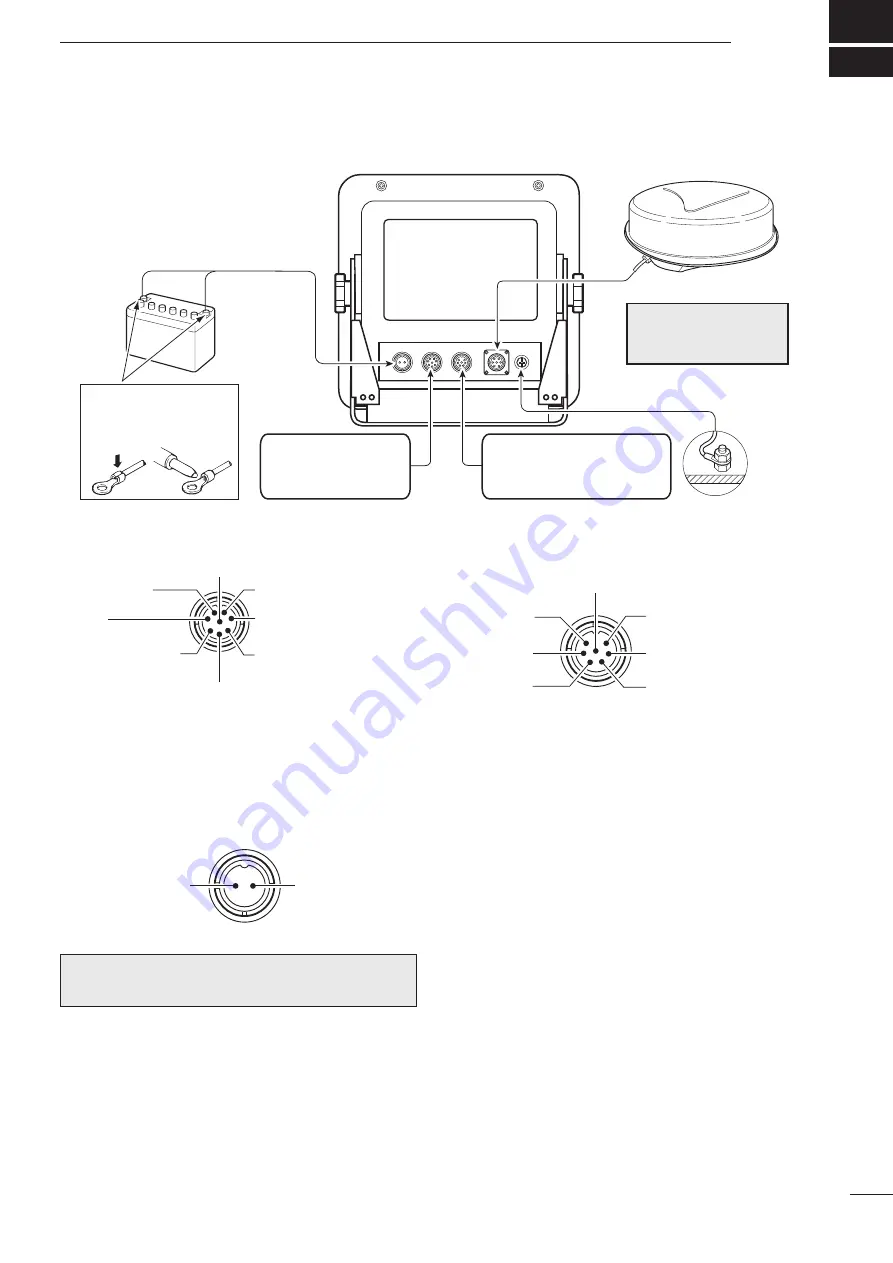
NMEA1:
AIS data input
Bearing data input
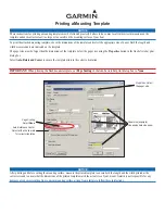
NMEA1 connection (Rear panel view)
NMEA2 connection (Rear panel view)
q
AIS input (+)
w
RXD
(FW_UP)
i
GND
r
NMEA 1 input (–)
or AUX input (–); DATA
e
NMEA 1 input (+)
or AUX input (+); DATA
u
AIS input (–)
y
N+1 input (–)
or AUX input (–); CLOCK
t
N+1(+); data input
or AUX input (+); CLOCK
■
Power source requirement
D
DC power source
DC input
Ground
The display unit is designed for connection to any
power source if the voltage is 10.2–42 V DC, so that a
12, 24, or 32 V DC battery can be used without a
DC-DC converter, or any internal modifications.
•
DC power cable connection
CAUTION
:
Incorrect cable connection will dam-
age the display unit.
Connect the supplied DC power cable as shown in the
diagram.
■
Ground connection
To prevent electrical shocks and other problems, ground the display unit through the [GND] terminal. For best re-
sults, connect a heavy gauge wire or strap to the nearest grounding point on the boat. The distance between the
[GND] terminal and the ground point should be as short as possible.
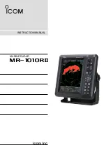
q
NMEA 2
output (+)
w
NMEA 2
output (–)
e
NMEA 2
input (+)
u
GND (Speed sensor)
y
Speed sensor
input
t
Regulated 5 V output.
(20 mA Max.)
r
NMEA 2 input (–)
(Rear panel view)
NMEA 1/2 inputs/NMEA 2 output: 4800 bps, AIS input: IEC61162-2 38400 bps