
T
1.296NM
O:01
O:01
0.566NM
S0672
˚
EBL/VRM1
EBL/VRM2
R
R
S0162
˚
3
(1)
NM
2530
˚
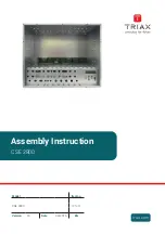
TM
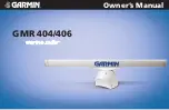
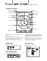
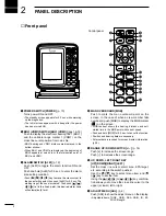
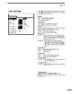
Heading indicator
Mode indicator*
5
Cross line cursor
EBL1/2
VRM1/2
MOB symbol
Fixed range rings*
1
Fixed ring range readout*
1
EBL1/VRM1, EBL2/VRM2
readouts*
4
Tuning level indicator
Screen range readout
Heading line
Alarm zone*
2
Own ship vector indicator
Waypoint marker*
3
■
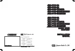
Display information
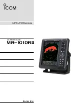
MR-570R
OPERATING GUIDE
*
1
Appears when the “RING” of the FUNCTION menu is
turned ON.
*
2
Appears when the alarm function is in use.
*
3
Appears when the “WPT” of the FUNCTION menu is
turned ON. To display the waypoint marker, bearing data
and NMEA data with 0183 format is necessary.
*
4
This area may differ depending on DATA DISP selection in
the FUNCTION menu. Nautical miles (NM) and kilometres
(KM) can be selected in the INT.SETTING menu as the dis-
tance unit.
*
5
North-up (N UP) and Course-up (C UP) screens require ex-
ternal bearing data. True Motion (TM) screen requires bear-
ing data and LOG or position data.
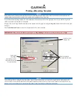
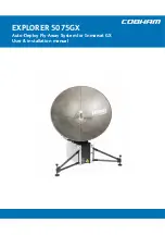
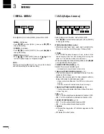
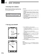
■
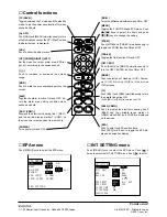
BRILL menu
Push [BRILL] to select the brilliance adjustment menu.
■
ADJ (Adjust) menu
Push [ADJ] to select the adjustment menu.
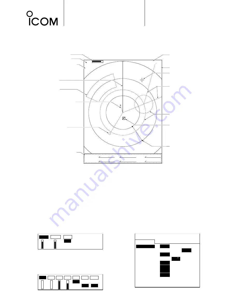
■
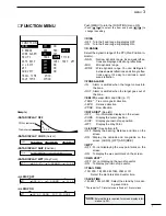
Function menu
Push [MENU] to select the function menu.
RING
D.RANGE
ZONE ALARM
EBL/PI
DATA DISP
L/L DISP
WPT
OWN VECT
TRAIL TIME
SAVE TIME
FUNCTION
OFF
ON
NAR. MID.
WIDE
IN
OUT
TRUE
360
R
PT/SB
OFF
CURS SHIP WPT
OFF
ON
OFF
ON
OFF
ON
6MIN
15MIN
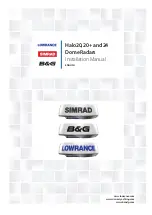
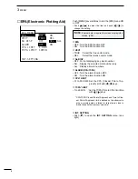
TUNE
GAIN SEA RAIN IR ES PULSE
ON
ON LP
OFF
OFF SP
A
U
T
O
A
U
T
O
BRILL.
CONTR. DISP.
POSI
NEGA
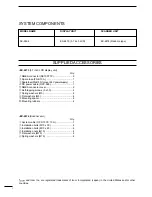
Summary of Contents for MR-570R
Page 3: ...INSTRUCTION MANUAL MARINE RADAR MR 570R ...
Page 36: ...30 9 INSTALLATION AND CONNECTIONS THIS PAGE IS INTENDED TO BE BLANK ...
Page 45: ...15 39 TEMPLATE 160 mm 6 5 16 91 mm 3 19 32 EX 2473 TEMPLATE ...
Page 46: ...40 ...
Page 47: ...Ship bow direction Radius is 6 mm 1 4 in EX 2474 Scanner unit template 45 5 mm 125 32 in ...
Page 48: ...90 5 mm 39 16 in 90 5 mm 39 16 in 150 5 mm 515 16 in 37 41 15 TEMPLATE ...
Page 49: ...1 1 32 Kamiminami Hirano ku Osaka 547 0003 Japan A 6014H 1EX q Printed in Japan 2001 Icom Inc ...