


4
2
!9
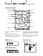
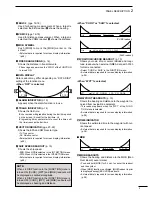
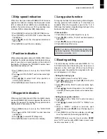
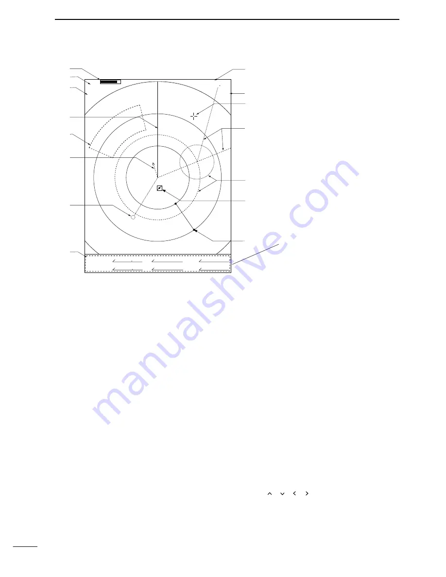
TUNING LEVEL INDICATOR
Shows the receiver tuning level.
@0
SCREEN RANGE READOUT (p. 16)
Shows the maximum range of the displayed screen.
• The range indicated is nautical miles (NM).
@1
FIXED RING RANGE READOUT (p. 16)
Shows the interval range of the fixed ring.
• This readout appears when the “RING” of the FUNC-
TION menu is turned ON.
@2
HEADING LINE (p. 11)
Heading line indicates the ships bow.
@3
ALARM ZONE (p. 19)
Shows the alarm zone.
•Appears when the alarm function is in use.
• External data is required for screen display information.
(p.38).
@4
OWN SHIP VECTOR INDICATOR
Shows the vector of your own ship.
@5
WAYPOINT MARKER (p. 15)
Shows the waypoint received from navigation
equipment.
• This marker appears when the “WPT” of the FUNCTION
menu is turned ON.
• External data is required for screen display information.
(p.38).
@6
EBL1/VRM1,EBL2/VRM2 READOUTS (pgs. 16-
18)
Shows the bearing of the displayed Electronic Bear-
ing Lines (EBL) and the distance of the displayed
Variable Range Markers (VRM).
• Nautical miles (NM) and kilometres (KM) can be se-
lected in the INT.SETTING menu as the distance unit.
@7
HEADING INDICATOR
Shows the heading bearing readout.
• The HDG readout indicates the bow of the ship’s bearing
in a clockwise direction from north.
• External data is required for screen display information.
(p.38).
@88
MODE INDICATOR
Head-up, Course-up (CUP), North-up (NUP) and
True Motion (TM) screens are available.
• External data is required for screen display information.
(p.38).
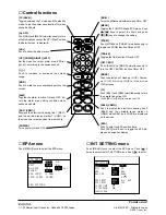
@9
CROSS LINE CURSOR
Used for measuring the bearing and distance, set-
ting the alarm zone, selecting the EPA targets, etc.
• Push
[
]/
[
]/
[
]
/[
] several times to move the cur-
sor.
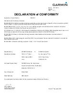
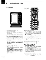
PANEL DESCRIPTION
■
Screen
S0672
˚
EBL/VRM1
EBL/VRM2
R
R
S0162
˚
3
(1)
NM
2530
˚
TM
T
1.296NM
O:01
O:01
0.566NM
@7
@8
@9
#0
#1
#2
#3
@2
@3
!9
@0
@1
@4
@5
@6
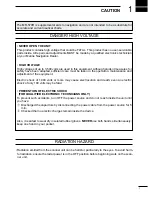
NOTE:
DATA display area may differ de-
pending on DATA DISP selection in
the FUNCTION menu.
Summary of Contents for MR-570R
Page 3: ...INSTRUCTION MANUAL MARINE RADAR MR 570R ...
Page 36: ...30 9 INSTALLATION AND CONNECTIONS THIS PAGE IS INTENDED TO BE BLANK ...
Page 45: ...15 39 TEMPLATE 160 mm 6 5 16 91 mm 3 19 32 EX 2473 TEMPLATE ...
Page 46: ...40 ...
Page 47: ...Ship bow direction Radius is 6 mm 1 4 in EX 2474 Scanner unit template 45 5 mm 125 32 in ...
Page 48: ...90 5 mm 39 16 in 90 5 mm 39 16 in 150 5 mm 515 16 in 37 41 15 TEMPLATE ...
Page 49: ...1 1 32 Kamiminami Hirano ku Osaka 547 0003 Japan A 6014H 1EX q Printed in Japan 2001 Icom Inc ...