q
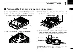
Turn the power OFF, then disconnect the DC power cable
from the transceiver’s main unit.
w
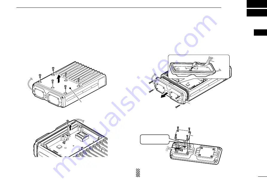
Unscrew the 6 top screws, then remove the top cover from
the transceiver’s main unit in the direction of the arrow.
Top cover
Main unit
e
Unscrew the screw that is attached to the chassis.
Front
r
Unscrew the 4 front screws, then remove the main unit
attachment from the main unit in the direction of the arrow.
• The flat cable should be carefully disconnected from the attachment.
Main unit attachment
Main unit attachment
Flat cable
t
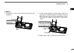
Unscrew the 4 screws, then remove the front plate from the
main unit attachment. Then unscrew the circuit board screw,
and disconnect the separation cable, if it is connected.
Main unit
attachment
Separation cable
Front plate
Remove the circuit
board screw.
IMPORTANT:
Set the top, chassis and front screws aside
as they are needed for the RMK-4 installation.
1
1
CONNECTION
1
2
3
4
5
6
7
8
9
10
11
12
13
14
15
16
■
Removing the transceiver’s main unit attachment


